Control device for electric motor drive device

a technology of electric motors and control devices, which is applied in the direction of motor/generator/converter stoppers, dynamo-electric converter control, dynamo-electric gear control, etc., can solve the problems of unnecessarily high processing load of voltage control sections, complex computation formulas, and high processing load of computations. to achieve the effect of reducing the processing load

Inactive Publication Date: 2011-03-31
AISIN AW CO LTD
View PDF7 Cites 43 Cited by
  • Summary
  • Abstract
  • Description
  • Claims
  • Application Information

AI Technical Summary

Benefits of technology

According to the configuration, the control signal corresponding to each of the AC electric motors is generated in each reference computation cycle. Thus, each of the plurality of AC electric motors can be driven smoothly. The modulation rate and the voltage command phase are derived sequentially for the plurality of AC electric motors on

Problems solved by technology

In the former case, the computation formula itself may be extremely complicated, and therefore the processing load for the computation

Method used


Image

  • Control device for electric motor drive device
  • Control device for electric motor drive device
  • Control device for electric motor drive device

Examples


first embodiment

1. First Embodiment

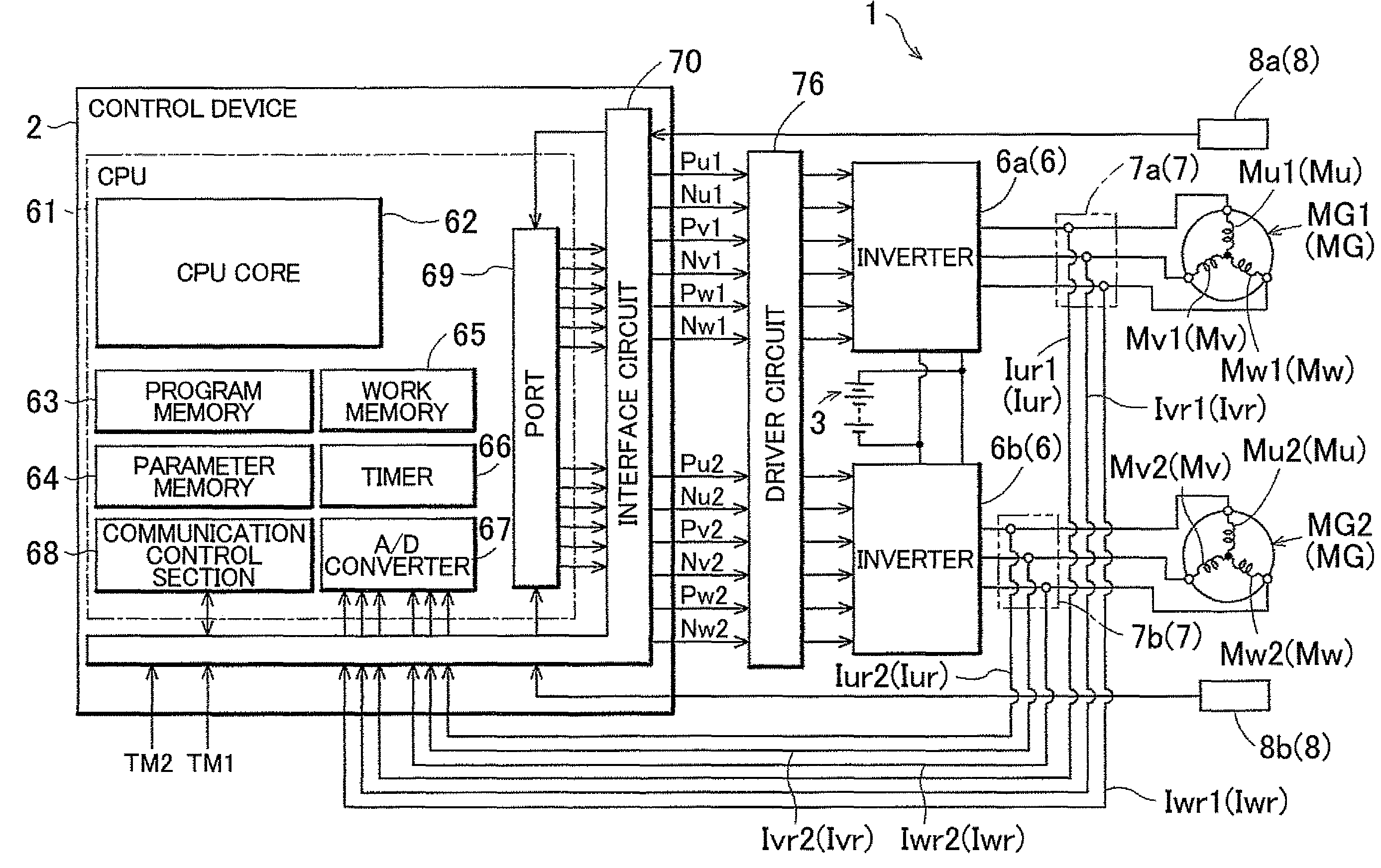
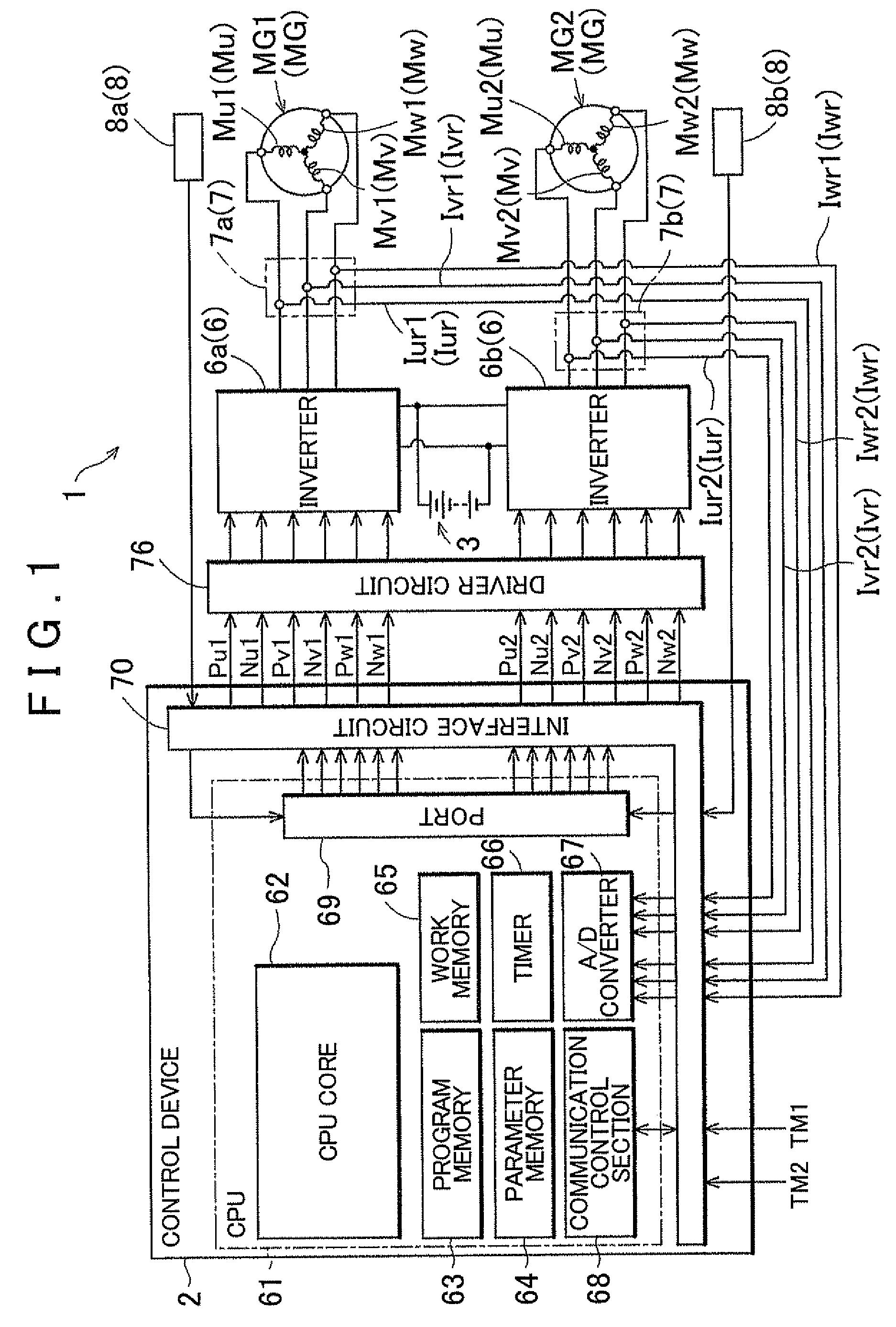
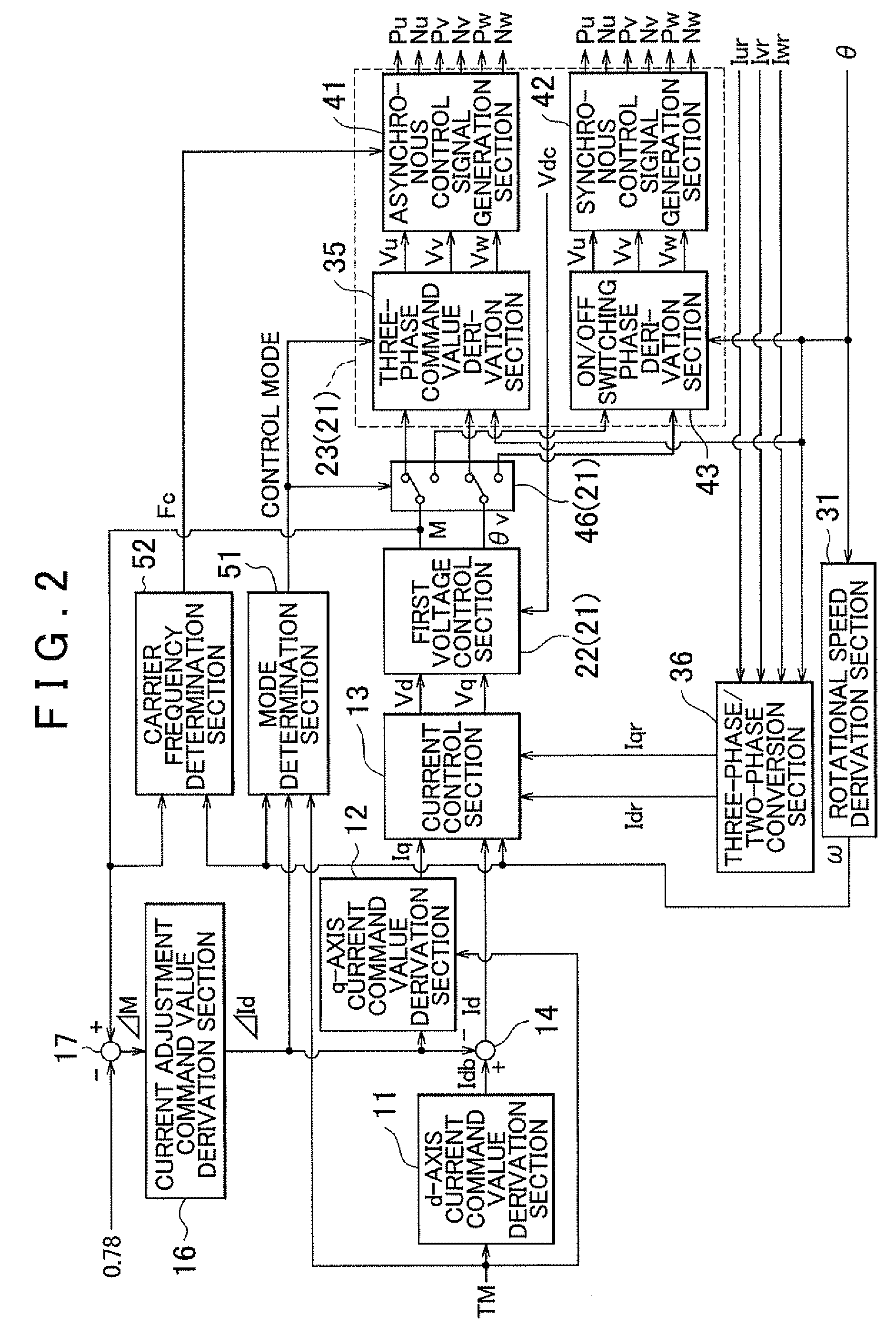
A control device 2 for an electric motor drive device 1 according to a first embodiment of the present invention will be described with reference to the drawings. In the embodiment, as shown in FIG. 1, the electric motor drive device 1 is configured as a device that controls driving of two interior permanent magnet synchronous electric motors MG1 and MG2 (IPMSMs, hereinafter occasionally collectively referred to simply as “electric motors MG”) which are each an AC electric motor that operates on three-phase AC. The electric motors MG are each configured to operate also as a generator as necessary. The electric motors MG are each used as a drive power source for electric vehicles, hybrid vehicles, or the like, for example. The electric motor drive device 1 includes inverters 6 that convert a DC voltage Vdc into an AC voltage to supply the AC voltage to the electric motors MG In the embodiment, in addition, as shown in FIG. 2, the control device 2 controls the elect...

second embodiment

2. Second Embodiment

The control device 2 for the electric motor drive device 1 according to a second embodiment of the present invention will be described. Also in the embodiment, the electric motor drive device 1 is configured as a device that controls driving of an interior permanent magnet synchronous electric motor MG which is an AC electric motor that operates on three-phase AC. The hardware configuration of the electric motor drive device 1 and the control device 2, the software configuration of the control device 2, and the relationship between the computation cycles of the respective functional sections of the control device 2 according to the embodiment are the same as those in the above first embodiment. The second embodiment is different from the above first embodiment in that only one electric motor MG is provided to be controlled by the electric motor drive device 1, although not shown. Accordingly, procedures of the electric motor control process are partly different f...


PUM


Abstract

A control device that controls an electric motor drive device. The control device is configured with a first voltage control section that derives a modulation rate representing a ratio of an effective value of the voltage command values to the DC voltage and a voltage command phase. A second voltage control section generates a control signal for controlling the DC/AC conversion section on the basis of the modulation rate, the voltage command phase, and a magnetic pole position representing a rotational angle of a rotator of the AC electric motor. A computation cycle of the first voltage control section is set to be longer than a computation cycle of the second voltage control section.

Description

INCORPORATION BY REFERENCEThe disclosure of Japanese Patent Application No. 2009-228857 filed on Sep. 30, 2009 including the specification, drawings and abstract is incorporated herein by reference in its entiretyBACKGROUND OF THE INVENTION1. Field of the InventionThe present invention relates to a control device that controls an electric motor drive device, which includes a DC / AC conversion section that converts a DC voltage into an AC voltage to supply the AC voltage to an AC electric motor, using a vector control method.2. Description of the Related ArtAn electric motor drive device that converts a DC voltage from a DC power source into an AC voltage through an inverter serving as a DC / AC conversion section to drive an AC electric motor is generally used. Such an electric motor drive device may perform vector control (field oriented control: FOC) to supply a sinusoidal AC voltage to coils of the AC electric motor for respective phases in order to efficiently produce a torque. In ...

Claims


Application Information

Patent Timeline
IPC IPC(8): H02P21/14H02P5/74H02P21/00H02P21/12H02P21/22H02P27/04
CPCH02P5/74H02P21/06H02P21/0089H02P21/0021
Inventor NAKAMURA, MITSURUSHIMADA, ARINORISAHA, SUBRATAIWATSUKI, KENCHEN, ZHIQIAN
Owner AISIN AW CO LTD
Why Eureka
Try Eureka