Determination of a Relative Position of a Satellite Signal Receiver

a satellite signal and relative position technology, applied in the field of supporting the determination of a relative position of a satellite signal receiver, can solve the problems of wasting valuable time, expensive equipment required for such applications,

Inactive Publication Date: 2011-03-31
NOKIA CORP
View PDF6 Cites 9 Cited by
  • Summary
  • Abstract
  • Description
  • Claims
  • Application Information

AI Technical Summary

Benefits of technology

[0032]By using an adjustable filter for a relative positioning of a satellite signal receiver, the quality of the positioning can be improved, since the optimal filter properties may depend on the presence or absence of a motion of the satellite signal receiver and on the kind of a current motion.
[0034]For example, the state space of the filter could be selected depending on the movement of the satellite signal receiver. The filter could then be adjusted to have a state space including rate-of-change components only in case the information on a movement of the satellite signal receiver indicates a change of the position of the satellite signal receiver relative to the reference station. Omitting a rate-of-change component in the first place when not required has the advantage of a faster convergence of the filter solution.
[0037]In one embodiment, the filter is adjusted by using a lower process noise in case the information on a movement of the satellite signal receiver indicates no change of the position of the satellite signal receiver relative to the reference station and a higher process noise in case the information on a movement of the satellite signal receiver indicates a change of the position of the satellite signal receiver relative to the reference station.
[0039]If the process noise is assumed to be constant, the filter may in the worst case diverge, which prevents an initialization of ambiguities and results in losing valuable time. With an adaptive process noise, in contrast, the perturbation of the accuracy of the relative positioning solution can be reduced and the filter may also be stabilized instantly after acceleration in the relative position.
[0047]The measurements may comprise carrier-phase measurements on satellite signals and / or other measurements, like code phase measurements. Carrier-phase measurements enable the device to perform a high-accuracy positioning of the satellite signal receiver.
[0050]The invention can be used with any kind of satellite signals, in particular, though not exclusively, with satellite signals transmitted in a GNSS, like GPS, GLONASS, GALILEO, SBAS, QZSS, LAAS or a combination of these. LAAS makes use of pseudolites instead of true satellites, but these pseudolites are to be understood to be covered as well by the term satellite as used in this application. LAAS has the advantage that it enables the use of a carrier- or code-phase based positioning under indoor conditions as well.

Problems solved by technology

The equipment required for such applications is expensive and meant, therefore, only for professional use.
If the process noise is assumed to be constant, the filter may in the worst case diverge, which prevents an initialization of ambiguities and results in losing valuable time.

Method used


Image

  • Determination of a Relative Position of a Satellite Signal Receiver
  • Determination of a Relative Position of a Satellite Signal Receiver
  • Determination of a Relative Position of a Satellite Signal Receiver

Examples


first embodiment

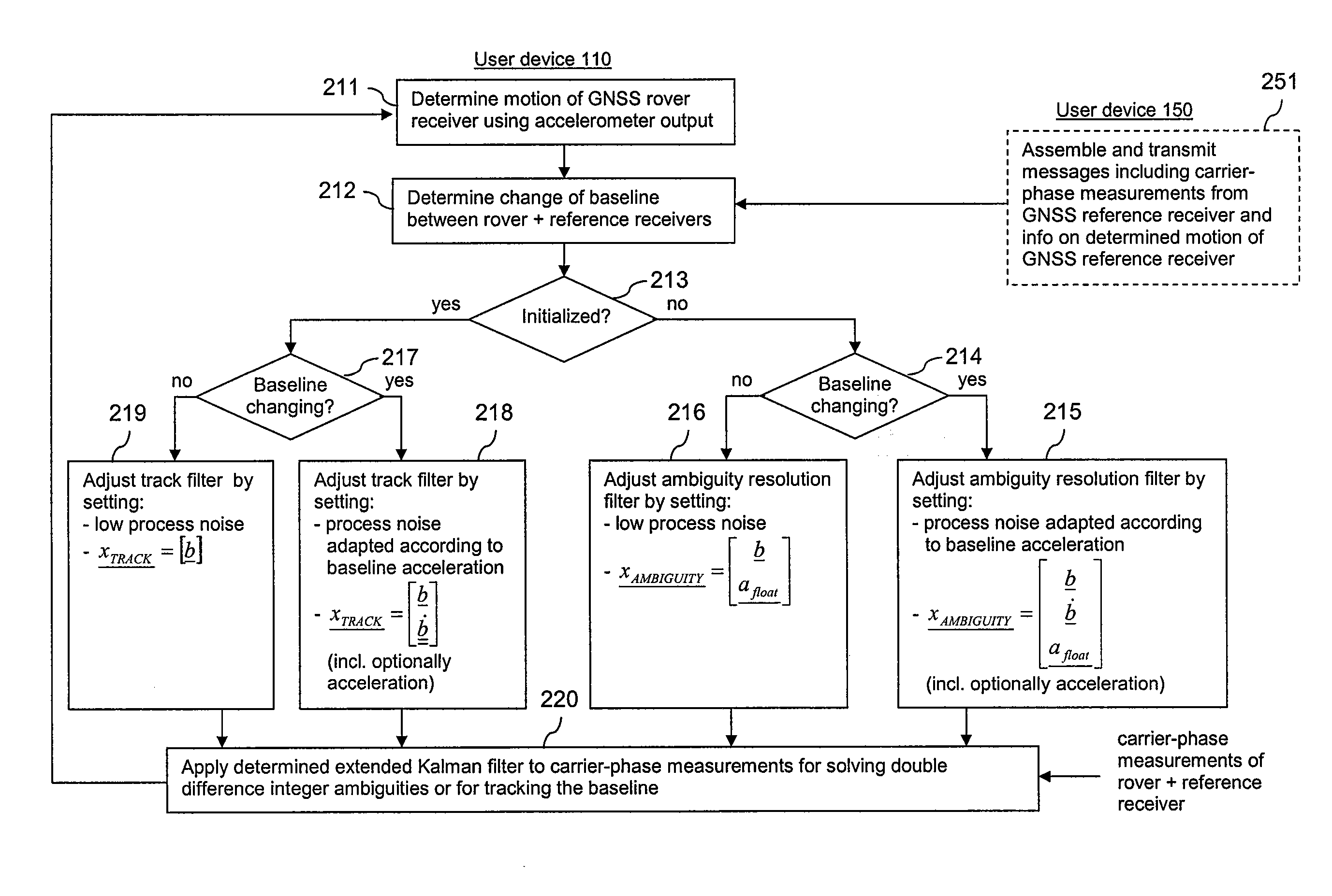
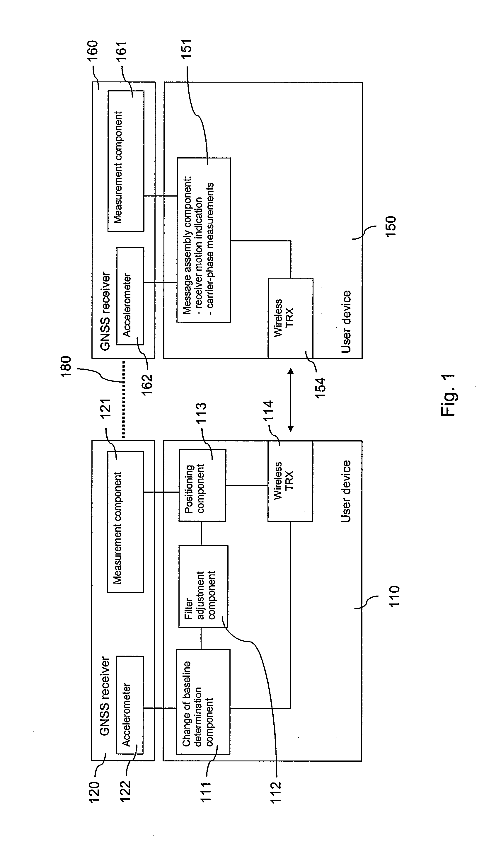
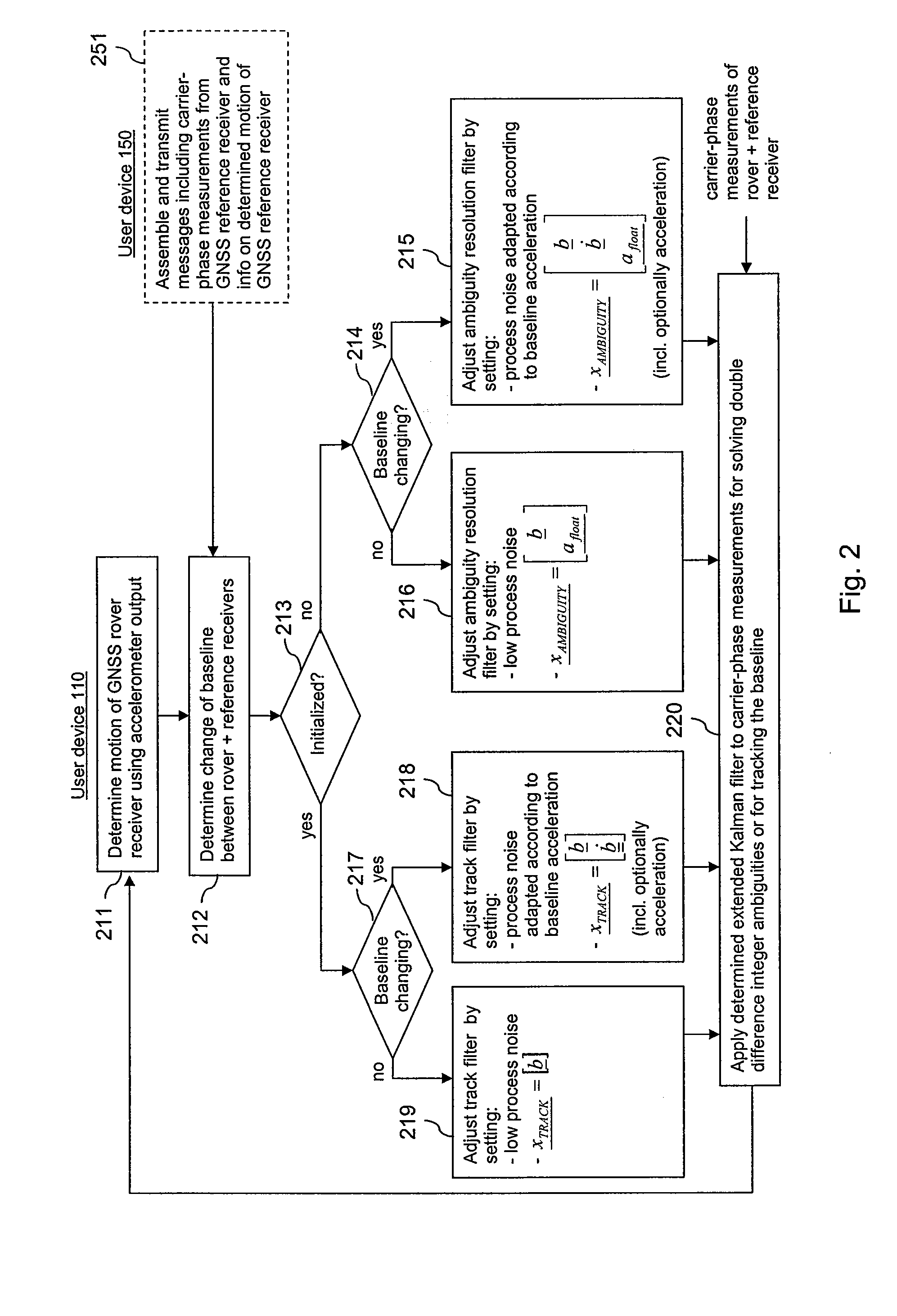
[0059]FIG. 1 is a schematic block diagram of a system, which enables an adaptive filtering for determining and tracking a baseline between two GNSS receivers in accordance with the invention.

[0060]The system comprises two user devices 110, 150, for example mobile phones or laptops.

[0061]Each of the user devices 110, 150 is connected to a GNSS receiver 120, 160. The GNSS receivers 120, 160 are accessory devices that can be linked to a respective user device 110, 150 using any suitable link, like a physical connection or a Bluetooth® link, etc. Thus, the GNSS receivers 120, 160 could be moved by a user separately from the user devices 110, 150. Alternatively, the GNSS receivers 120, 160 could be integrated in the user devices 110, 150.

[0062]Each of the GNSS receivers 120, 160 comprises a measurement component 121, 161, which is able to perform carrier phase measurements on received satellite signals of at least one GNSS, for instance Galileo or GPS. Each of the GNSS receivers 120, 160...

second embodiment

[0120]FIG. 6 is a schematic block diagram of a system, which enables an adaptive filtering for determining and tracking a baseline between two GNSS receivers in accordance with the invention.

[0121]The system comprises a wireless communication terminal 610 and a network element 650.

[0122]The terminal 610 can be for instance a mobile phone.

[0123]The terminal 610 comprises a processor 611 and, linked to this processor 611, a memory 612, a transceiver (TRX) 617, a user interface 618, an accelerometer 619 and a GNSS receiver 620. It is to be understood that the GNSS receiver 620 could also be a separate device. In case the GNSS receiver 620 can be moved separately from the terminal 610, however, the accelerometer 619 has to be integrated in or physically connected to the GNSS receiver 620. GNSS receiver 620 functions as a rover receiver.

[0124]The processor 611 is configured to execute implemented computer program code. The memory 612 stores computer program code, which may be retrieved b...


PUM


Abstract

For enhancing the quality of a relative positioning, a filter is adjusted depending on information on a movement of a satellite signal receiver. A position of the satellite signal receiver is determined relative to a reference station using the filter, wherein measurements on satellite signals received by the satellite signal receiver and measurements on satellite signals provided for the reference station are used as input to the filter. The measurements for the reference station may be received in messages which are assembled and provided for transmission and which may include in addition an indication of a current movement of the reference station.

Description

CROSS REFERENCE TO RELATED APPLICATION[0001]This application is a divisional of copending application Ser. No. 11 / 743,070 filed on May 1, 2007 and claims domestic priority under 35 U.S.C. §120.FIELD OF THE INVENTION[0002]The invention relates to supporting the determination of a relative position of a satellite signal receiver.BACKGROUND OF THE INVENTION[0003]An absolute positioning of a device is supported by various Global Navigation Satellite Systems (GNSS). These include for example the American Global Positioning System (GPS), the Russian Global Navigation Satellite System (GLONASS), the future European system Galileo, the Space Based Augmentation Systems (SBAS), the Japanese GPS augmentation Quasi-Zenith Satellite System (QZSS), the Locals Area Augmentation Systems (LAAS), and hybrid systems. The satellites of these systems are also referred to as space vehicles (SV).[0004]The constellation in GPS, for example, consists of more than 20 satellites that orbit the earth. Each of ...

Claims


Application Information

Patent Timeline
Patent Type & Authority Applications(United States)
IPC IPC(8): G01S19/42G01S19/05G01S5/14G01S19/07G01S19/11G01S19/12G01S19/31G01S19/55
CPCG01S19/55
Inventor WIROLA, LAURISYRJARINNE, JARI
Owner NOKIA CORP
Why Eureka
Try Eureka