Image capturing apparatus, image displaying method and recording medium, image displaying program being recorded thereon

a technology of image capturing and image displaying, which is applied in the field of image capturing apparatus, image displaying method and recording medium, and image displaying program being recorded thereon, can solve the problems of difficult to display the graded scale in real time as an over layer onto the captured image, and computational complexity exceedingly high, etc., to achieve simple structure, reduce computational complexity, and low cost

Inactive Publication Date: 2011-03-31
NAT INST FOR QUANTUM & RADIOLOGICAL SCI & TECH +1
View PDF5 Cites 29 Cited by
  • Summary
  • Abstract
  • Description
  • Claims
  • Application Information

AI Technical Summary

Benefits of technology

[0035]The present invention is characterized as generating the graded scale to be used for indicating the dimension of the physical object in the captured image; correcting the graded scale shape by adding the distortion to the generated graded scale in the similar degree to the distortion caused by the distortion aberration at the image capturing optical part; and displaying the corrected shape-distorted graded scale as an over layer onto the captured image. According to the present invention, as the graded scale shape is corrected by adding the distortion to the generated graded scale in the similar degree to the distortion caused by the distortion aberration, it will be appreciated that the computational complexity can be smaller that the case of applying the shape correction to the captured image, and that the graded scale can be displayed in real time as an over layer onto the captured image even by using the general purpose computer such as PCs.
[0036]According to the present invention, it will be appreciated that the image capturing apparatus may be provided with inexpensive price because there is no need for any endoscope position and direction sensor as disclosed in Patent Literature 3 or any special sensor such as range image sensor disclosed in Patent Literature 4.
[0037]According to the present invention, it will be also appreciated that the image capturing apparatus may be provided with a simplified structure because there is no need for any complex structure for controlling precisely the physical position such as the measurement light scanning means disclosed in Patent Literature 3.

Problems solved by technology

There are such problems as described below by referring to Patent Literatures in the above proposed technologies.
As the computational complexity required in processing those calculations becomes extremely higher, it is difficult to display the graded scale in real time as an over layer onto the captured image in case of using a general purpose computer such as personal computers (hereinafter referred to as “PC”) for processing those calculations.
Thus, as in the similar manner to the proposed technology described in Patent Literature 1, there is such a problem that the computational complexity becomes extremely higher and that it is difficult to display the graded scale in real time as an over layer onto the captured image in case of using a general purpose computer.
In addition, as it is required to install the endoscope position and direction detecting sensor at the endoscope in order to detect the position of the top of the endoscope, there is such a problem that the price of the endoscope may become higher.
Owing to this configuration, there is such a problem that a mechanism for controlling precisely the physical position of the laser light source is required, and thus, the structure of the image capturing apparatus becomes more complex.

Method used


Image

  • Image capturing apparatus, image displaying method and recording medium, image displaying program being recorded thereon
  • Image capturing apparatus, image displaying method and recording medium, image displaying program being recorded thereon
  • Image capturing apparatus, image displaying method and recording medium, image displaying program being recorded thereon

Examples


first embodiment

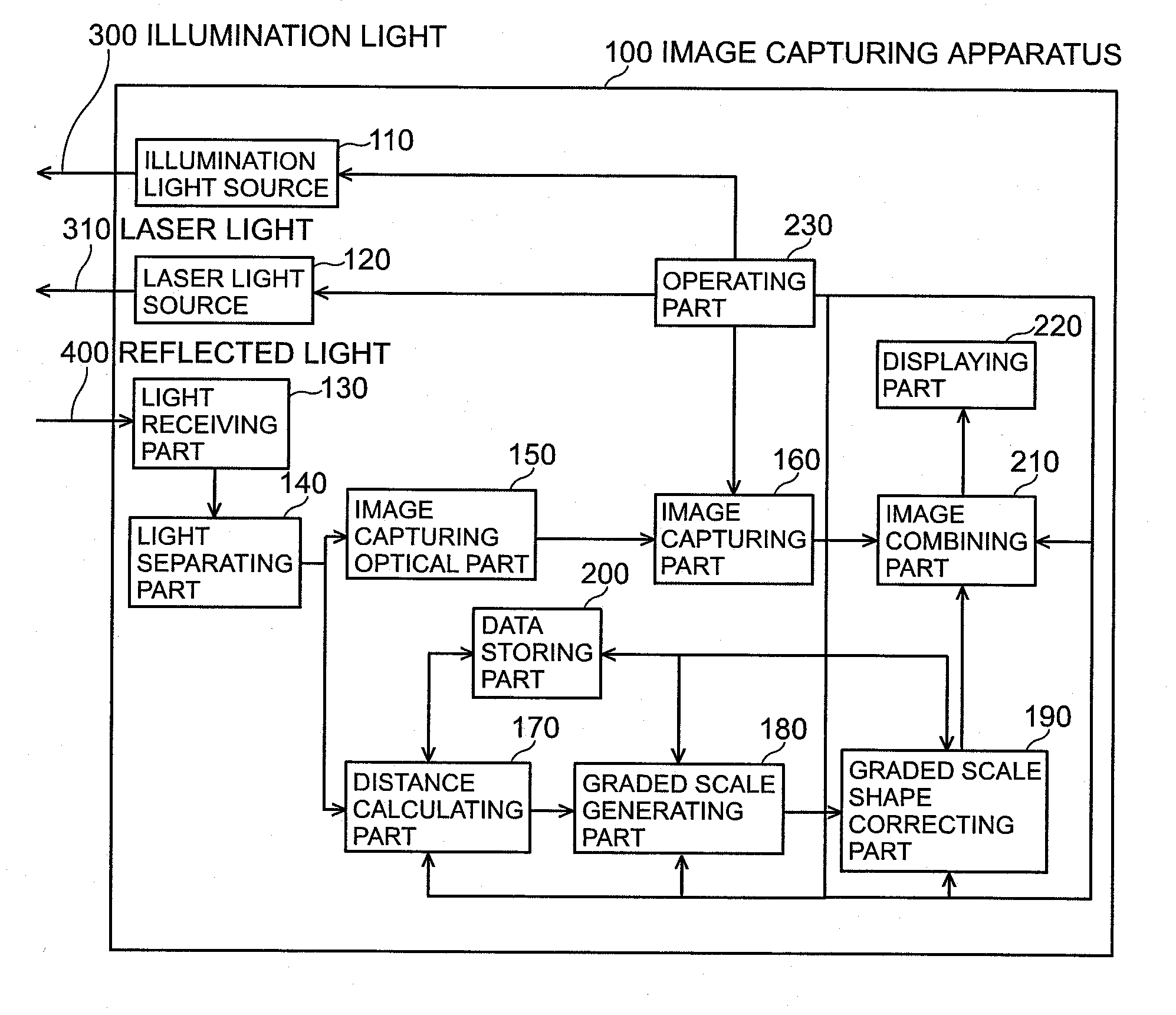
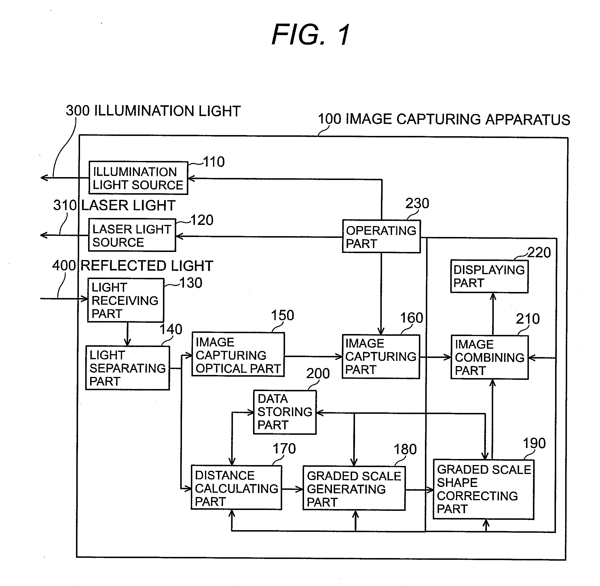
[0050]FIG. 1 is a block diagram showing the structure of the image capturing apparatus of the first embodiment according to the present invention. As shown in FIG. 1, the image capturing apparatus 100 in this embodiment comprises the illumination light source 110, the laser light source 120, the light receiving part 130, the light separating part 140, the image capturing optical part 150, the image capturing part 160, the distance calculating part 170, the graded scale generating part 180, the graded scale shape correcting part 190, the data storing part 200, the image combining part 210, the displaying part 220 and the operating part 230.

[0051]The illumination light source 110, receiving the instruction issued from the operating part 230 for irradiating the illumination light, starts irradiating the light including at least a part of the wavelength region of the visible light (from 380 nm to 750 nm) or its full wave length region of the visible light as the illumination light 300 p...

embodiment 2

[0092]FIG. 6 is a block diagram showing the structure of the image capturing apparatus of the second embodiment according to the present invention. As shown in FIG. 5, the image capturing apparatus 500 in this embodiment has such differences from the image capturing apparatus 100 of the first embodiment as shown in FIG. 1 as the displacement calculating part 520 is added, and the distance calculating part 170 is replaced by the distance calculating part 510, and the graded scale generating part 180 is replaced by the graded scale generating part 530. Note that other structural elements are the same as those in the image capturing apparatus 100 shown in FIG. 1 and they will not be described in detail.

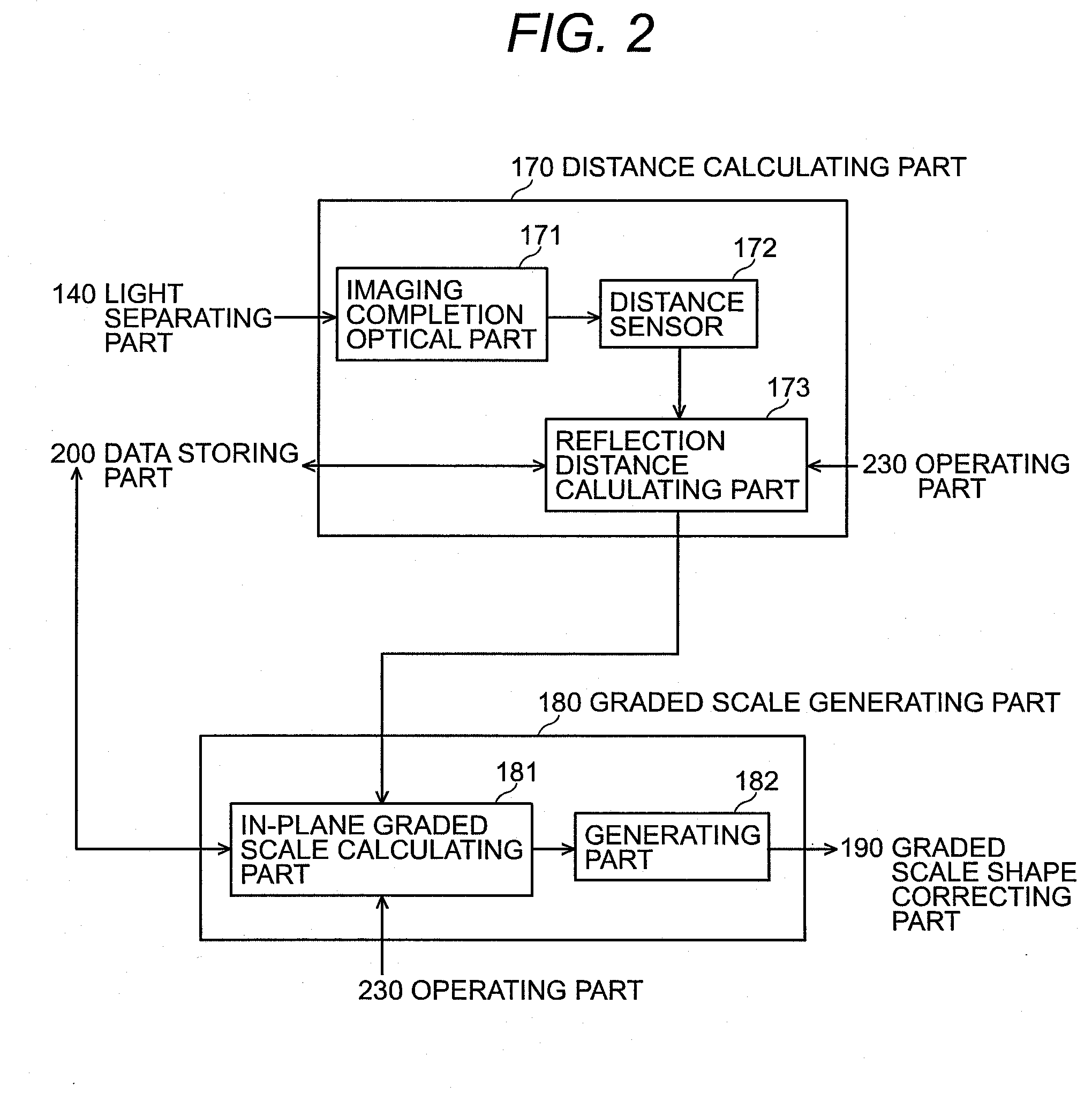
[0093]FIG. 6 is a block diagram describing the detail structure of the distance calculating part 510, the displacement calculating part 520 and the graded scale generating part 530 shown in FIG. 6. As shown in FIG. 6, the distance calculating part 510 has the imaging completion optical p...


PUM


Abstract

An image capturing apparatus for capturing the image of the physical object and displaying the captured image is provided for combining and displaying in real time the shape-distorted graded scale with the captured image, the apparatus comprising a graded scale generating part for generating the graded scale to be used for indicating the dimension of the physical object in the captured image; a data storing part for storing the data for correction to be used in order to correct the graded scale shape by adding the distortion to the generated graded scale in the similar degree to the distortion caused by the distortion aberration; a graded scale shape correcting part for generating the shape-distorted graded scale by correcting the graded scale shape according to the data for correction; and an image combining part for combining the generated shape-distorted graded scale with the captured image, and displays the captured image combined with the shape-distorted graded scale.

Description

BACKGROUND OF THE INVENTION[0001]The present invention relates to a technology used in an image capturing apparatus which enables to capture the image of a physical object and display the captured image for displaying a graded scale to be used for indicating the dimension of the physical object so as to be displayed as an over layer onto the captured image.[0002]In recent years, the image capturing apparatus to capture the image of the physical object under observation and to display the captured image in real time on the displaying part such as Liquid Crystal Display and organic / inorganic EL (electro-Luminescence) display has been widespread, for example, including endoscope, digital still camera and digital video camera. Such image capturing apparatus complete s imaging of the reflected light from the physical object as the object image on the imaging sensor such as CCD and CMOS by using the image capturing optical part comprising lens system, and then captures the completed objec...

Claims


Application Information

Patent Timeline
Patent Type & Authority Applications(United States)
IPC IPC(8): H04N7/18
CPCA61B1/042A61B2019/5231G02B23/2484G06T7/0065H04N5/232G02B23/2415G01C11/04G01B11/022G06T2207/10072G06T3/40A61B2090/373H04N23/63H04N25/61
Inventor OKA, KIYOSHIEDAYA, MASAHIRO
Owner NAT INST FOR QUANTUM & RADIOLOGICAL SCI & TECH
Why Eureka
Try Eureka