Continuous-rate clock recovery circuit

a clock signal and recovery circuit technology, applied in the direction of digital transmission, pulse automatic control, pulse technique, etc., can solve the problems of static phase offset, steady state errors at the output of the phase detector, leakage of the charge pump integrator, etc., and achieve low jitter transfer bandwidth and stable circuit

Active Publication Date: 2011-03-31
ANALOG DEVICES INC
View PDF15 Cites 34 Cited by
  • Summary
  • Abstract
  • Description
  • Claims
  • Application Information

AI Technical Summary

Benefits of technology

[0018]The present invention is in part, based on the realization that significant advantages and benefits may be achieved by utilizing separate integrators in the DLL and PLL of a D / PLL system. Among the advantages are a more stable circuit; low jitter transfer bandwidth; and scaling of the bandwidth of drift compensation with data rate frequency.

Problems solved by technology

However, circuit imperfections such as leakage currents and finite output device impedances make the charge pump a leaky integrator.
Leaky integrators lead to steady state errors at the output of the Phase Detector 8.
Steady state errors in CDRs result in static phase offset, where the sampling is no longer in the middle of the data eye.
Leaky integrators may also cause the D / PLL to lose frequency lock in the presence of a long sequence of consecutive identical digits.
Otherwise, the system risks going unstable.
The Phase Shifter 7 implementation is limited because it has a restricted range of tunable delays, it is not readily amenable to covering multiple octaves of data rates, and its bandwidth must change with frequency to maintain the same gain and phase shift range.

Method used


Image

  • Continuous-rate clock recovery circuit
  • Continuous-rate clock recovery circuit
  • Continuous-rate clock recovery circuit

Examples


Embodiment Construction

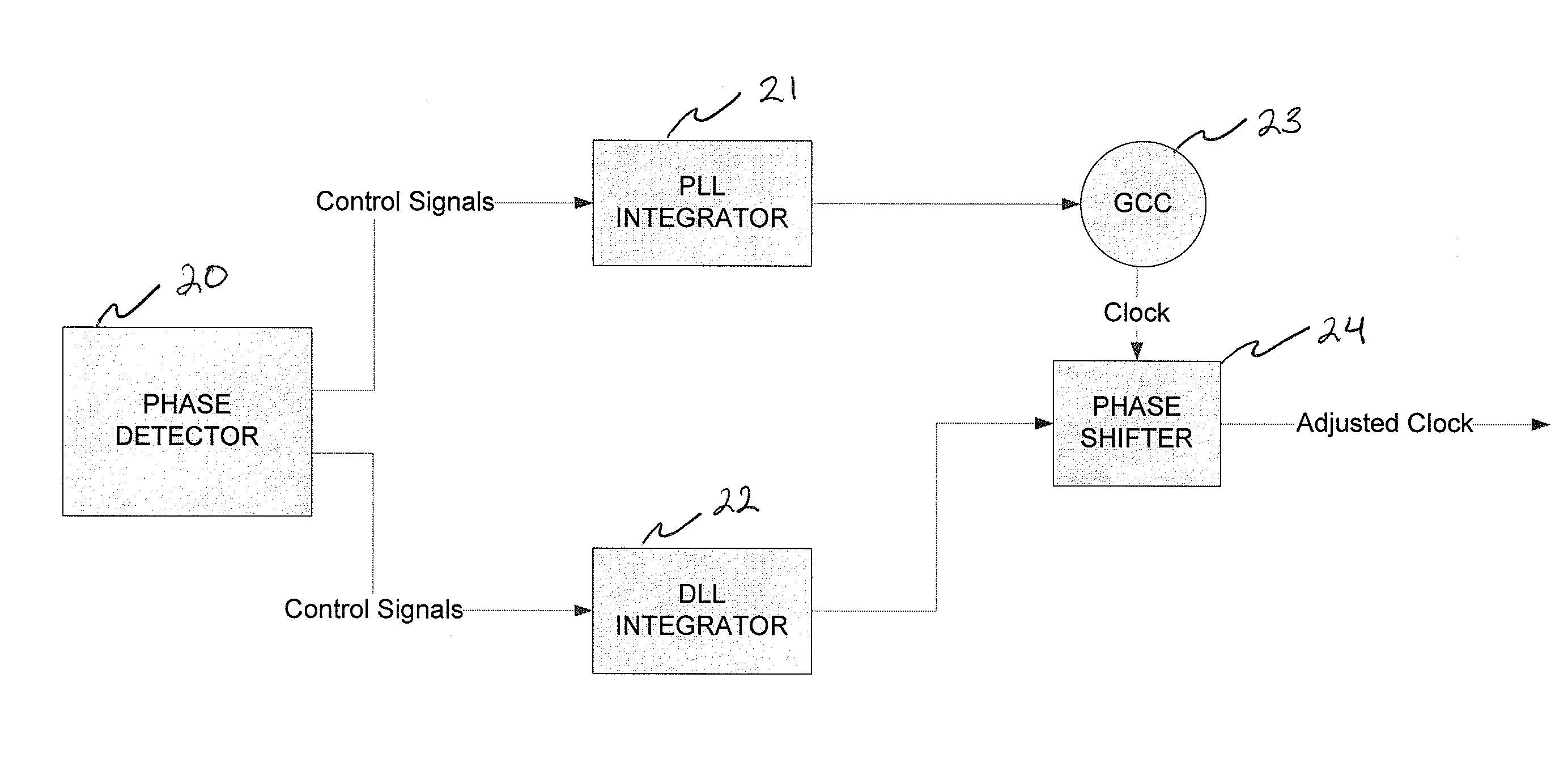
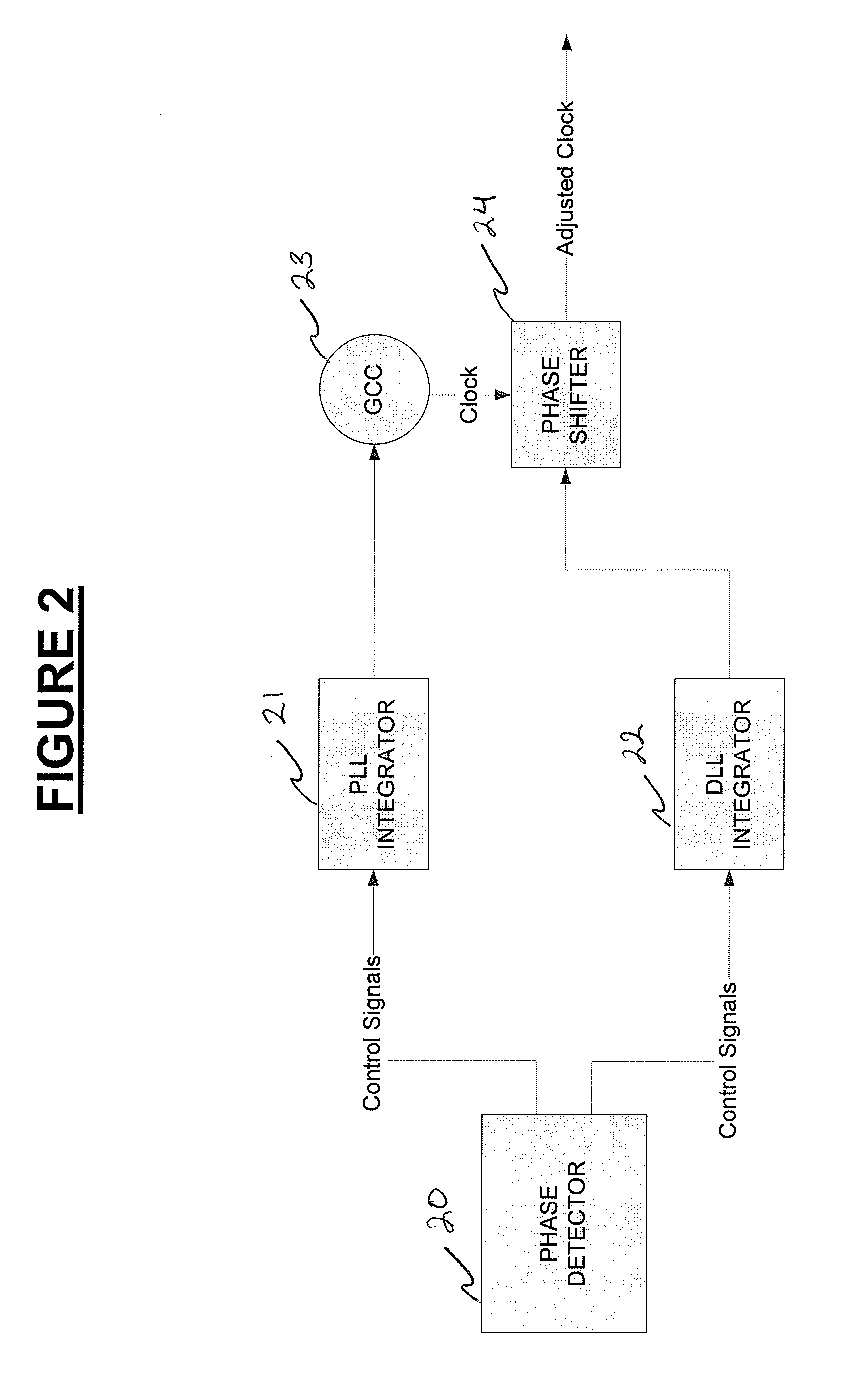
[0041]The present invention is in part, based on the realization that significant advantages and benefits may be achieved by utilizing separate integrators in the DLL and PLL of a D / PLL system. FIG. 2 illustrates a D / PLL system according to an exemplary embodiment of the present invention. The D / PLL in FIG. 2 includes a Phase Detector 20, a PLL Integrator 21, a DLL Integrator 22, a Clock Generation Circuit (GCC) 23, and a Phase Shifter 24.

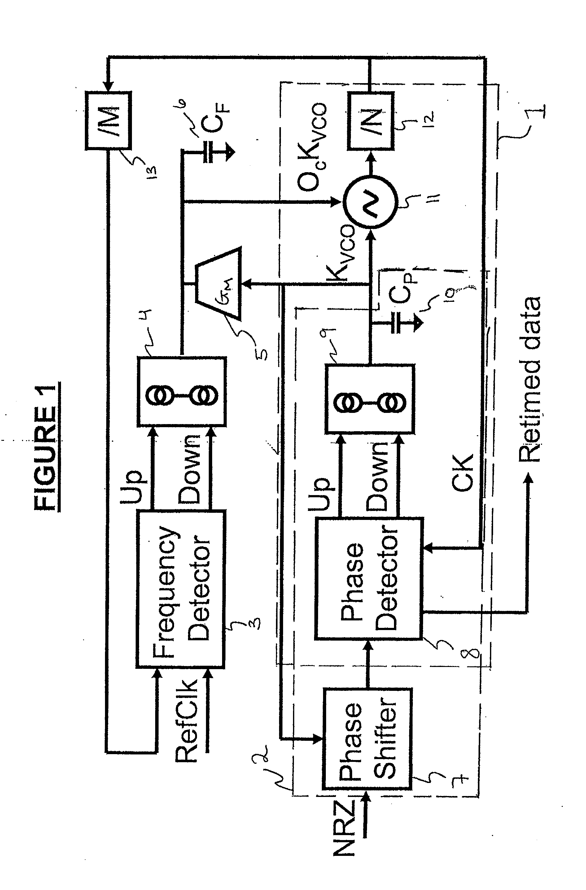
[0042]The PLL Integrator 21 and DLL Integrator 22 replace the phase charge pump PhCP 9 in the prior art D / PLL illustrated in FIG. 1. In this exemplary embodiment, the separation of PLL Integrator 21 and DLL Integrator 22 is implemented in the digital domain.

[0043]FIG. 3 illustrates a digital D / PLL system 30 according to another exemplary embodiment of the present invention. In this embodiment, the digital integrators are implemented as digital accumulators.

D / PLL Circuit

[0044]Referring to FIG. 3, the D / PLL 30 system includes a Data Sampler 31, a 1:M...


PUM


Abstract

A continuous-rate clock and data recovery circuit includes a delay locked loop with a first integrator and a phase locked loop with a separate integrator. The delay locked loop and the phase locked loop are in a dual loop architecture. The first integrator is a digital accumulator that wraps upon exceeding a maximum or minimum value. The second integrator is a digital accumulator that saturates at its maximum or minimum value.

Description

FIELD OF THE INVENTION[0001]Systems, apparatuses, and methods consistent with the present invention relate to generating a clock signal, and more particularly to a clock recovery circuit for generating a continuous-rate clock signal.BACKGROUND OF THE INVENTION[0002]A data signal is sometimes transmitted without a clock signal (e.g., a non-return to zero (NRZ) signal). NRZ signals are advantageous in that they require only half the bandwidth necessary to transmit both a data signal and a clock signal. However, a clock signal is still useful to sample the data signal and recover the data.[0003]One way to sample the data signal is to use a recovered clock signal. A clock signal may be recovered by generating a reference clock signal, and then phase-aligning and frequency-aligning the generated clock signal to the data signal. This is often referred to as clock and data recovery (CDR). A continuous-rate CDR is a CDR that can operate over a wide range of data rates.[0004]A phase-locked l...

Claims


Application Information

Patent Timeline
Patent Type & Authority Applications(United States)
IPC IPC(8): H04L7/00
CPCH03L7/235H04L7/0337H04L7/0025
Inventor KENNEY, JOHN G.
Owner ANALOG DEVICES INC
Why Eureka
Try Eureka