

Radiation imaging apparatus and imaging control device
a technology of radiation imaging apparatus and control device, which is applied in the field of radiation imaging apparatus, can solve the problems of two-shot method, long imaging time, and the disclosure of a technique capable of improving energy separation performance and reducing motion artifacts, and achieves short time, low cost, and high separation performance.
- Summary
- Abstract
- Description
- Claims
- Application Information
AI Technical Summary
Benefits of technology
Problems solved by technology
Method used
Image

Examples
first embodiment
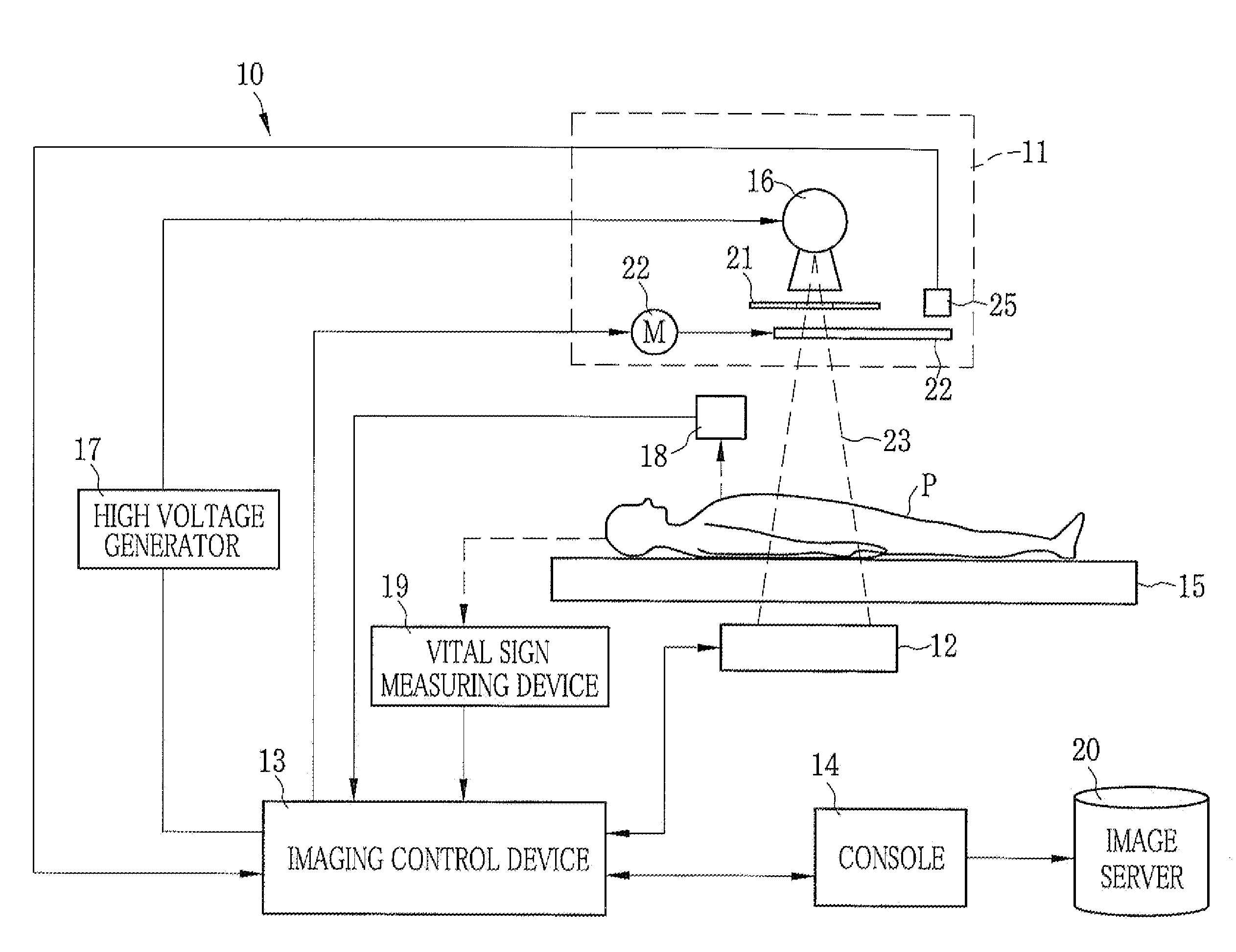
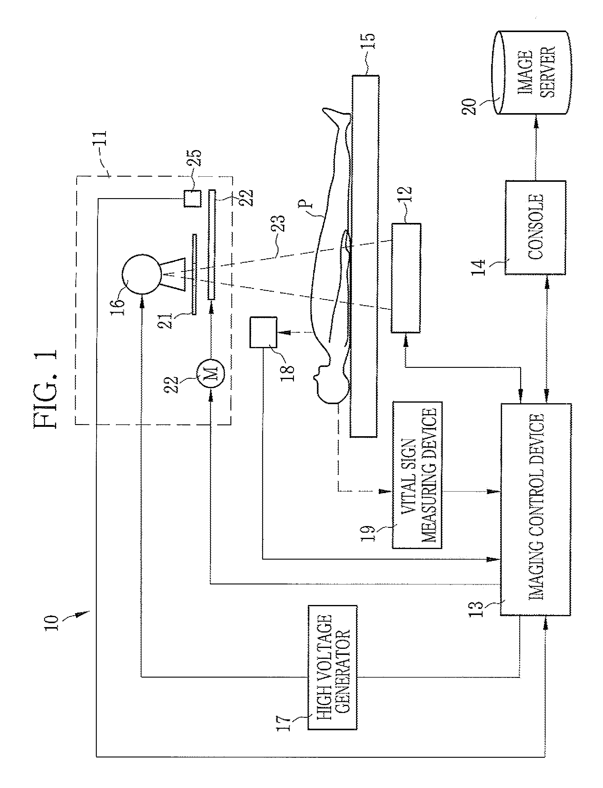
[0048]In FIG. 1, a radiation imaging apparatus 10 is composed of a radiation source 11 for generating and emitting radiation, a radiation image detector 12 for receiving the radiation passed through a subject P to detect a radiation image, an imaging control device 13 for controlling the radiation source 11 and the radiation image detector 12, and a console 14 for inputting operation instructions such as exposure conditions and instructions for imaging to the imaging control device 13. The radiation imaging apparatus 10 is, for example, a laying-type imaging apparatus for capturing images of the subject P laid down on a patient table 15.
[0049]The radiation source 11 is provided with a radiation tube, for example, an X-ray tube 16 having a cathode filament and an anode target. A high voltage is applied between the cathode and the anode, so that thermal electrons released from the filament hit the target. Thus, X-ray is generated. The target has a disc-like shape, and rotates while th...
second embodiment
[0115]In the first embodiment, the cardiac cycle and respiration are used as examples of the subject information. Alternatively, the body thickness may be used as the subject information. In this case, the area shifting cycle or shift cycle of the filter 22 may be determined in consideration of the body thickness. In other words, the imaging control device 13 determines the area shifting cycle of the filter 22 in accordance with the maximum exposure time determined based on the body thickness, regardless of the cardiac cycle or respiratory cycle.
[0116]For the energy subtraction imaging, the imaging control device 13 obtains the imaging time required for the two successive X-ray emissions, T1 and T2, based on or in accordance with the maximum exposure time. For example, in the case where the maximum exposure time for each of the high-energy X-ray emission T1 and the low-energy X-ray emission T2 is 0.08 seconds, the total maximum exposure time is 0.16 seconds. To calculate the imaging...
third embodiment
[0124]In the above embodiment, the filter, that is, a rotary plate is used as an example. In addition, a filter set 40 composed of multiple rotary plates may be used as shown in FIG. 13. The filter set 40 is composed of three filters 41 to 43. The filters 41 to 43 are composed of the rotation axes and motors 46 to 48, respectively, such that each of the filters 41 to 43 rotates individually with a predetermined area shifting cycle or shift cycle. As shown in FIG. 14, rotation centers of the filters 41 to 43 are respectively located on a line 49.
[0125]The filter 41 has two different filter areas 41a and 41b each located in a quadrant area of a circular rotary plate, and a transmission area 41c formed in a remaining semi-circular area thereof. A filter 42 has two different filter areas 42a and 42b each located in a quadrant area of a circular rotary plate, and a transmission area 42c formed in a remaining semi-circular area thereof. The filter 43 has two different filter areas 43a and...
PUM
| Property | Measurement | Unit |
|---|---|---|
| energy distribution | aaaaa | aaaaa |
| area | aaaaa | aaaaa |
| phase | aaaaa | aaaaa |
Abstract
Description
Claims
Application Information