
Steam turbine rotor and steam turbine using the same

a steam turbine and rotor technology, applied in the direction of turbines, machines/engines, manufacturing tools, etc., can solve the problems of deterioration of ultrasonic wave permeability, low productivity of large forged materials, and the inability to maintain the back wave, so as to achieve high reliability, improve reliability, and ensure long-term reliability

Inactive Publication Date: 2011-03-31
HITACHI LTD
View PDF9 Cites 2 Cited by
  • Summary
  • Abstract
  • Description
  • Claims
  • Application Information

AI Technical Summary

Benefits of technology

[0013]An object of the present invention is to provide a steam turbine rotor and a steam turbine that are highly reliable.
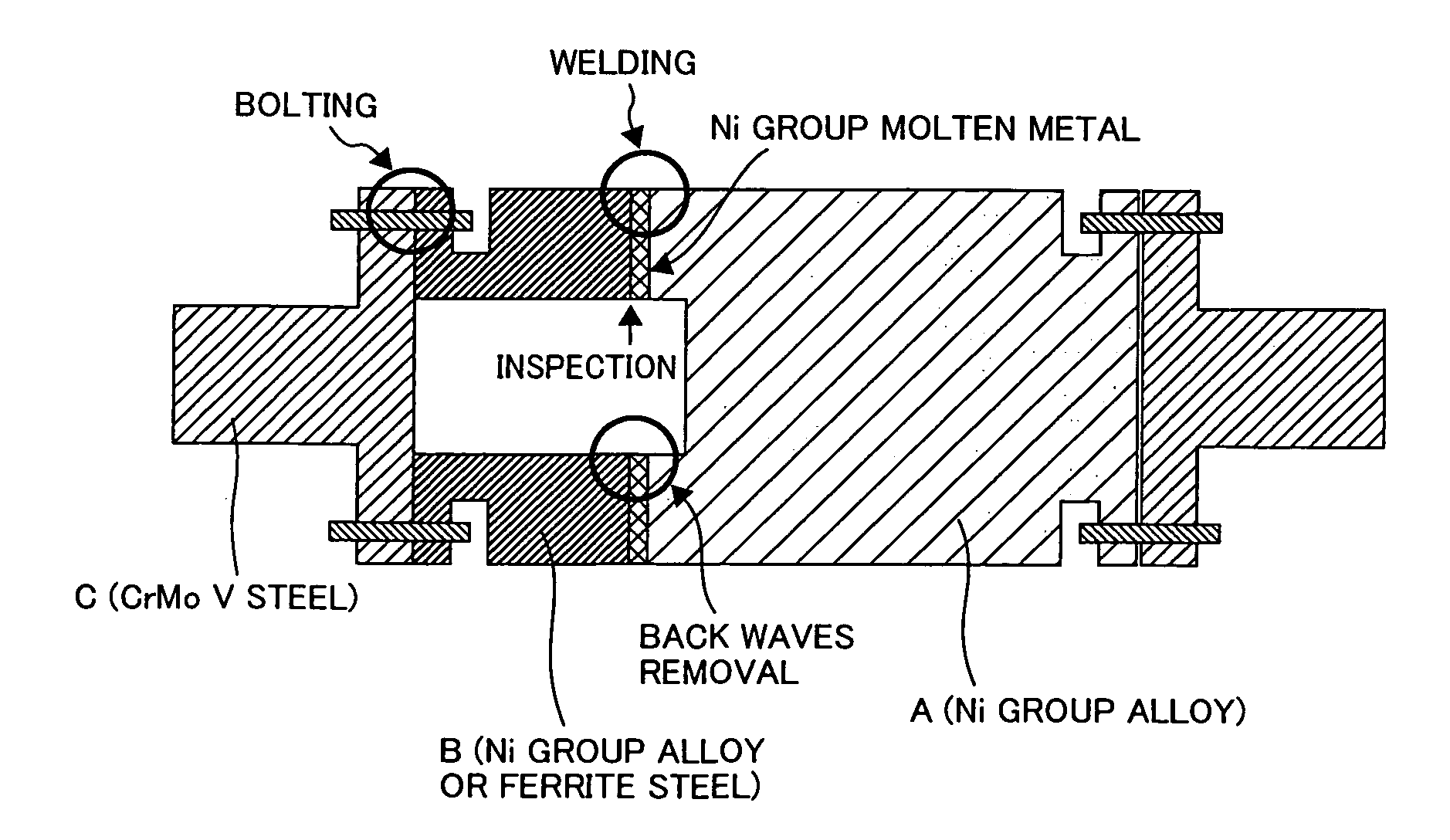
[0016]According to the present invention, there are no weld back waves at all on the inner surface, and the reliability can be improved by the inspection at the time of manufacture, though by removing the bolt at the time of the periodic inspection, the inner surface of the welded portion can be re-inspected, and the inspection at the time of the periodic inspection is executed, thus long term reliability can be ensured even further.
[0018]According to the present invention, a steam turbine rotor and a steam turbine that are highly reliable can be realized.

Problems solved by technology

The Ni group super-alloy is excellent in the high-temperature intensity, and even a forging material withstands steam at 700° C. or higher, though a problem arises that the productivity of a large forged material is low.
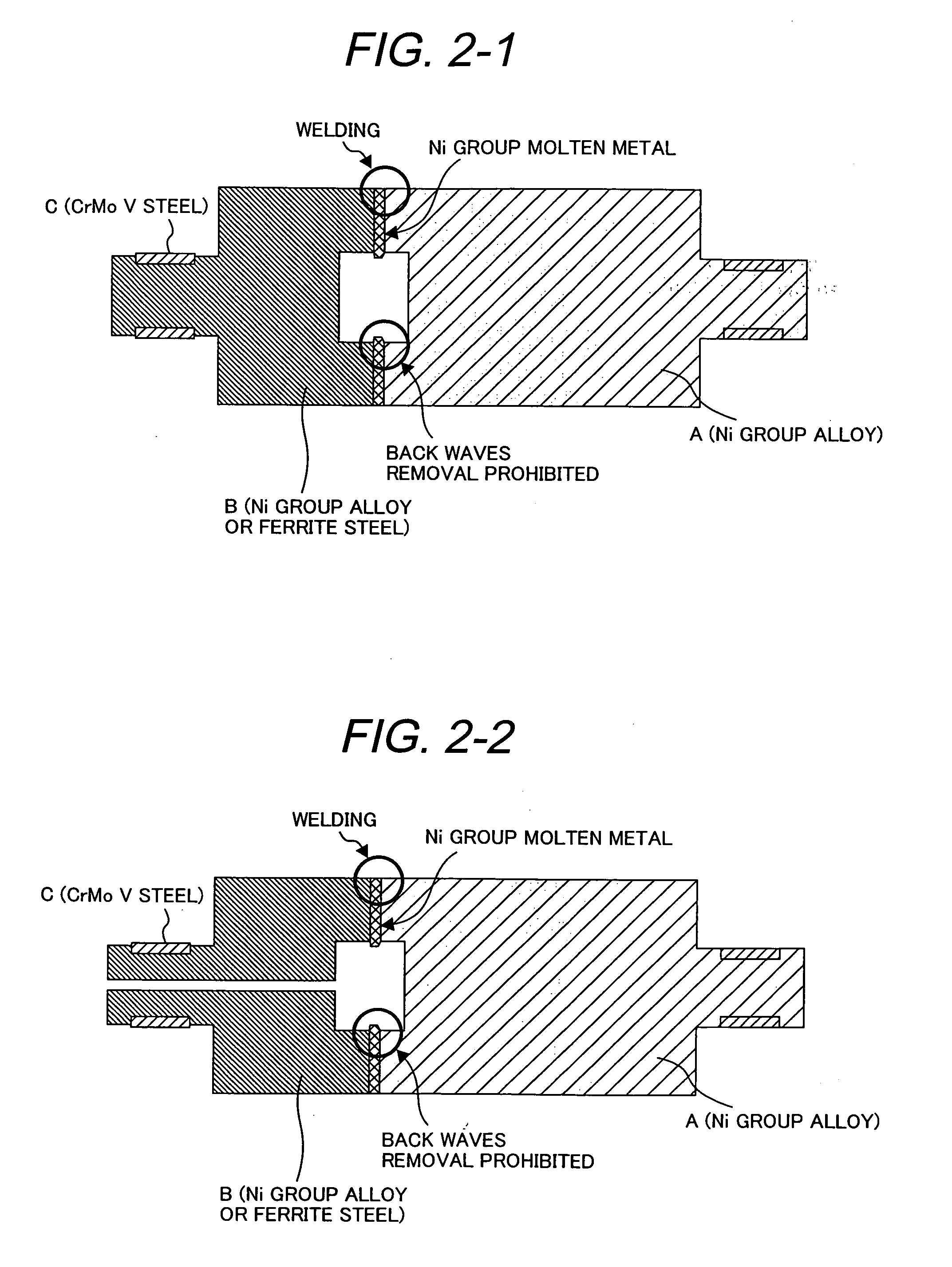
However, after welding, the back waves internally remaining cannot be removed, thus a problem arises that a state occurs where an internal defect remains.
Further, the Ni group super-alloy is bad in the ultrasonic wave permeability and in a welding metal composed of coarse particles, the ultrasonic wave permeability is deteriorated even more.
To join the Ni group super-alloy and ferrite steel, a welding metal of the Ni group super-alloy is generally used, so that in the aforementioned weld type rotor, the internal defect detection limit is lowered, thus causing a staying of the back waves and a reduction in reliability.
In addition to the weld joint, a rotor of the joint structure with a bolt is well-known, though strong tension is applied to the bolt portion, so that if the bolt portion rises in temperature, the bolt is subject to creep deformation and is loosened, so a bolt joint portion having a temperature limit and insurance reliability at 500° C. or higher is difficult.

Method used


Image

  • Steam turbine rotor and steam turbine using the same
  • Steam turbine rotor and steam turbine using the same
  • Steam turbine rotor and steam turbine using the same

Examples


embodiment

[0026]Table 1 shows the chemical components of the forging materials of the steam turbine rotor of the present invention that are used in the embodiment.

TABLE 1Chemical components of forging materials (mass %)MaterialnameCNiCrMoCoAlTiWNbVFX7000.034216001.31.702.00Bal. FeA2630.03Bal.206200.41.7000A1410.03Bal.19.010.201.581.38000FE010.170.21.01.0000000.2Bal. FeFE020.160.511.20.800000.10.2Bal. Fe

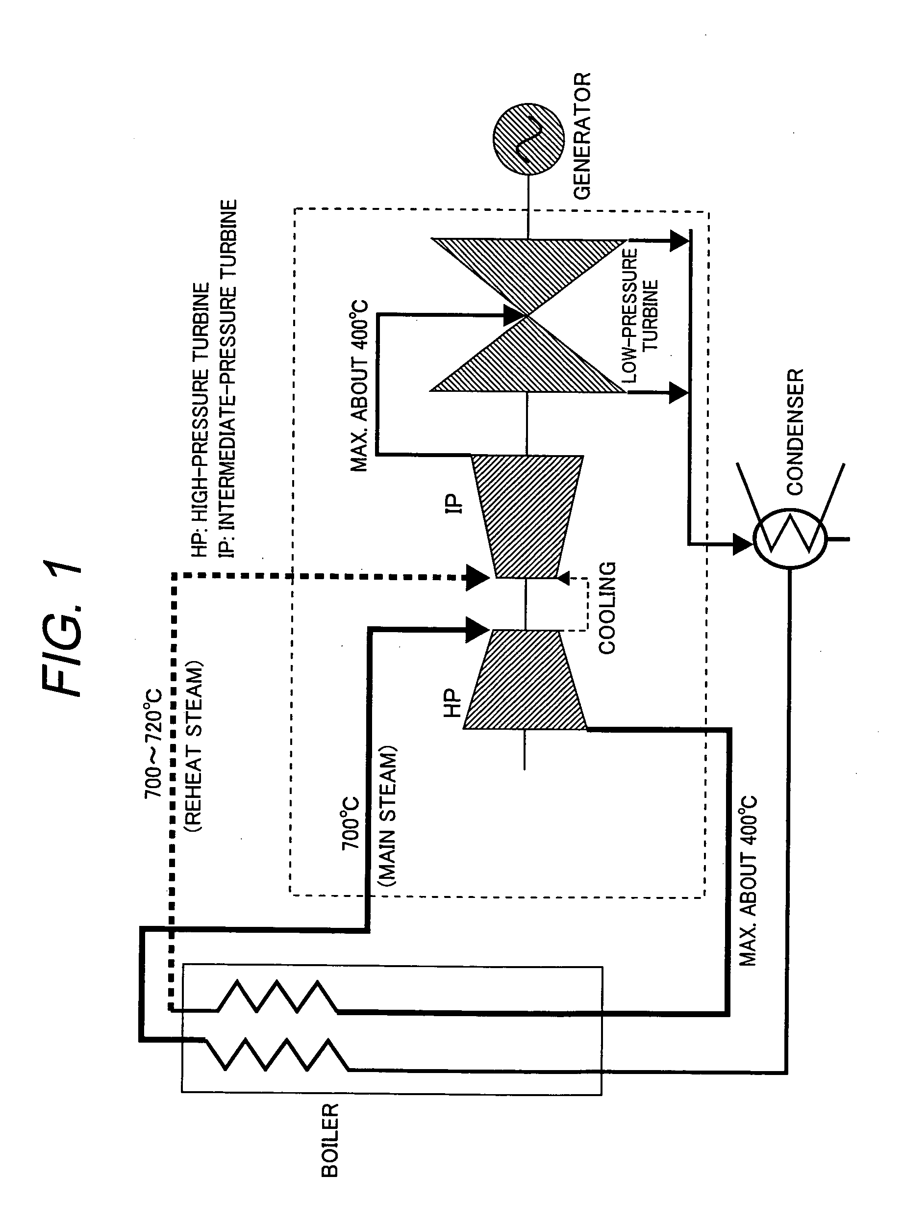
[0027]FIG. 1 shows a configuration example of the steam turbine plant to which the steam turbine rotor that is an embodiment of the present invention is applied. The main steam temperature is 700° C. and the main steam works in the high-pressure turbine (HP) and then is reduced in temperature to about 400° C. However, the steam is returned again to the boiler, is re-heated up to 720° C., and becomes reheat steam.

[0028]The pressure of the reheat steam is lower than that of the main steam, so that the burden imposed on the pressure resistant member of the steam turbine is almost the same as that ...


PUM

PropertyMeasurementUnit
temperatureaaaaaaaaaa
weightaaaaaaaaaa

Abstract

To provide a steam turbine rotor and a steam turbine which are highly reliable.The steam turbine rotor is characterized in that a forged material B having a hollow structure is joined to a forged material A of a Ni group super-alloy by welding, and weld back waves on an inner surface are removed, and the inner surface is smoothed, and a forging material C and a forging material B are joined to each other with a bolt.

Description

CLAIM OF PRIORITY[0001]The present application claims priority from Japanese Patent application serial no. 2009-221814, filed on Sep. 28, 2009, the content of which is hereby incorporated by reference into this application.BACKGROUND OF THE INVENTION[0002]1. Field of the Invention[0003]The present invention relates to a steam turbine rotor and a steam turbine using the same.[0004]2. Description of the Related Art[0005]To improve the power generation efficiency of a steam turbine power generation plant, a rise of the main steam temperature is valid. In correspondence with the rise of the main steam temperature, the temperature of a high-temperature part increases, so that a heat resistant material of a higher resistant temperature is necessary.[0006]In the steam turbine, a steel material such as 12-Cr steel has been used thus far, though by use of a Ni group super-alloy for a high-temperature portion of the turbine or boiler, the research and development of a high efficiency steam tu...

Claims


Application Information

Patent Timeline
Patent Type & Authority Applications(United States)
IPC IPC(8): F01D5/02
CPCB23K31/02B23K2201/001B23K2203/18F05D2300/132F01D5/066F05C2201/0466F01D5/063B23K2101/001B23K2103/18B23K2103/26
Inventor IMANO, SHINYADOI, HIROYUKISATO, JUN
Owner HITACHI LTD
Learn More