Flexible wireless network system and method of use

a wireless network and flexible technology, applied in the direction of amplifiers, electrical equipment, transmission, etc., can solve the problems of low power efficiency of mobile telecommunication equipment used in stationary communication units, low power efficiency of mobile telecommunication equipment, and the need for high quality rf signal radiated to open space, so as to efficiently amplify the signal strength of an input rf

Inactive Publication Date: 2011-03-31
JANG SEI JOO
View PDF7 Cites 11 Cited by
  • Summary
  • Abstract
  • Description
  • Claims
  • Application Information

AI Technical Summary

Benefits of technology

[0011]A flexible wireless network system adapted for switching to a desired frequency and efficiently amplifying signal strength of an input RF signal of the desired frequency in wireless communications while meeting ACLR requirements. The system includes an input source to receive the input RF signal, a input filter bank RF amplifier, a pre-distortion engine, a high gain amplifier connected to the pre-distortion engine, a filter module, a low gain amplif

Problems solved by technology

However, the power output efficiency of the mobile telecommunication equipment used in stationary communication units is notoriously “low” at about ten percent.
One of the reasons for such low power efficiency of mobile telecommunication equipment relative to other power applications is that the quality of RF signal radiated to open space needs to be extremely high.
Most PAs exhibit some degree of nonlinearity near the PA's saturation point, which causes an increase in the spectral growth of the output power density and leads to distortion of the ACLR and EVM of the output signal.
The conventional Pas operate with in the linear region to satisfy the ACLR and EVM requirements, but consequent

Method used


Image

  • Flexible wireless network system and method of use
  • Flexible wireless network system and method of use
  • Flexible wireless network system and method of use

Examples


Embodiment Construction

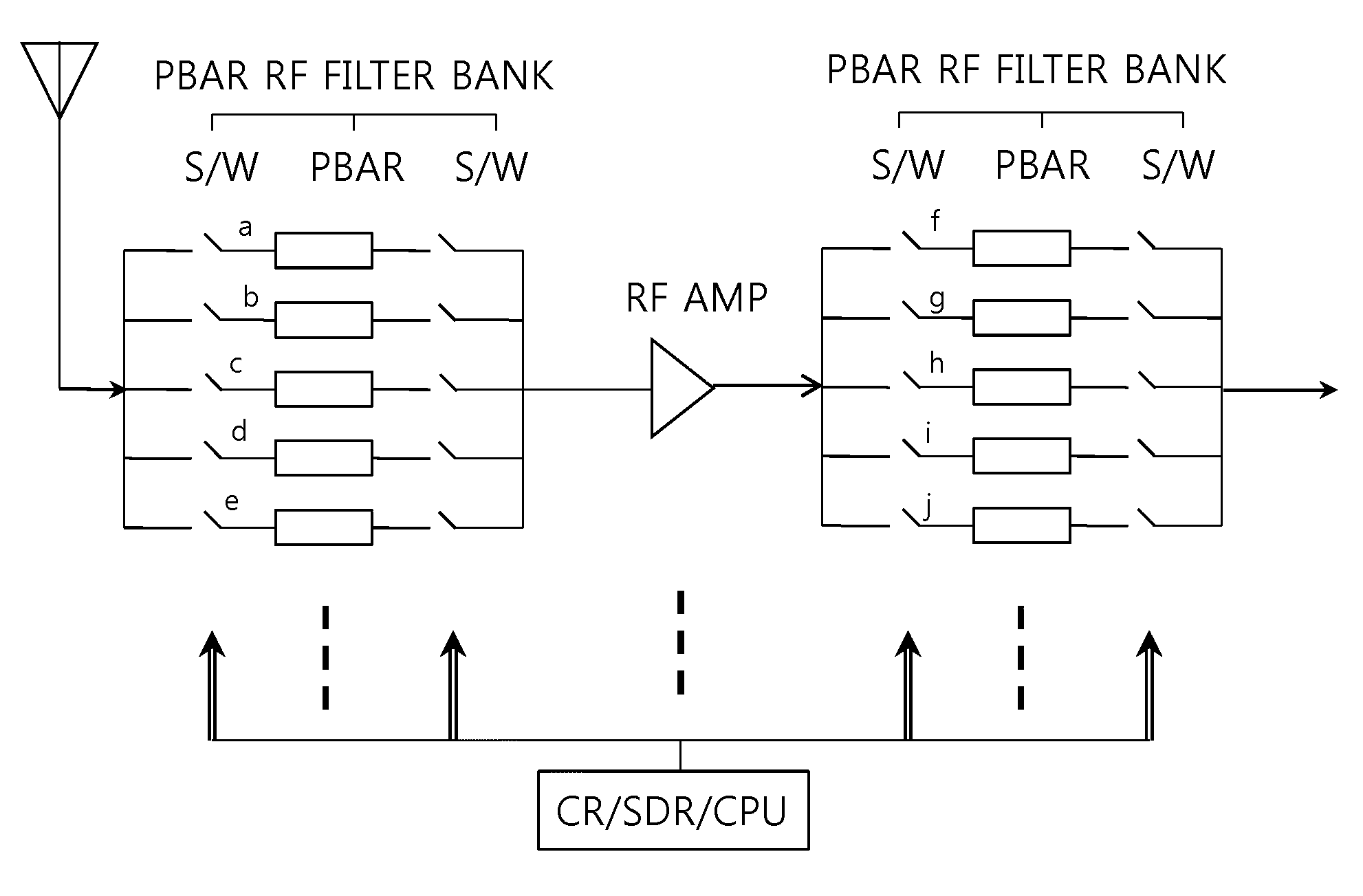
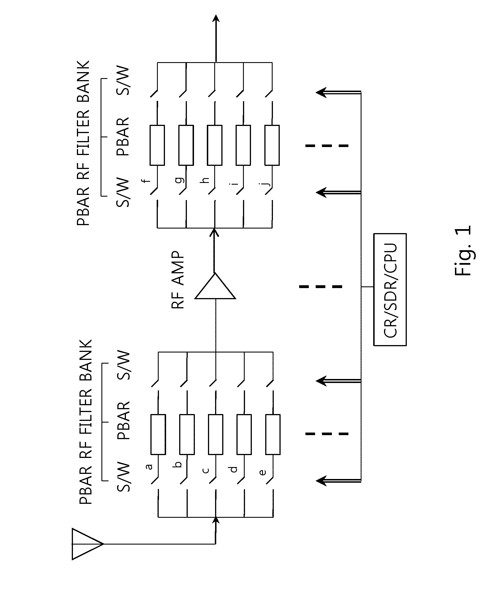
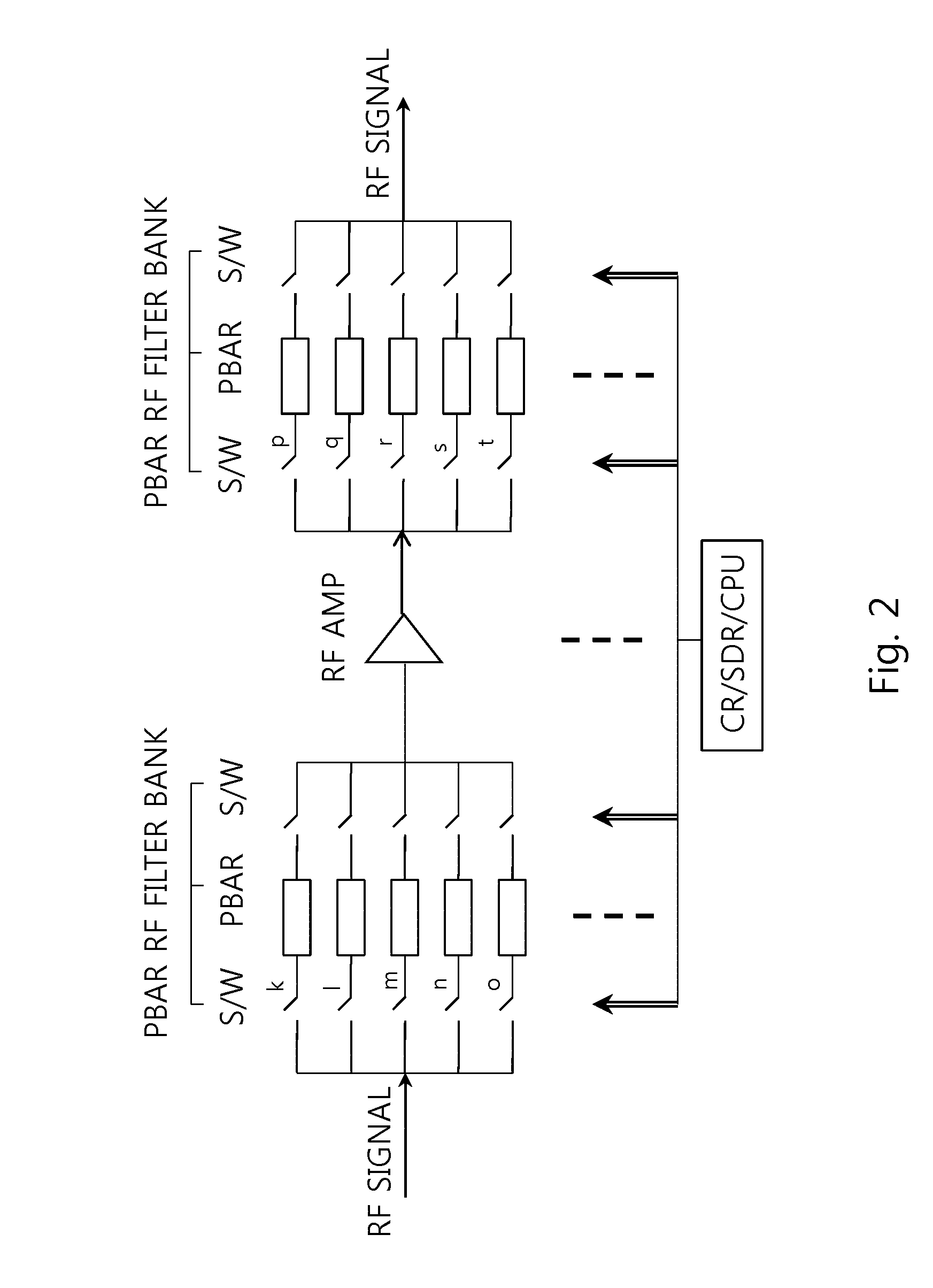
[0036]The present invention is a flexible wireless network system and method of use. The flexible wireless network includes advanced switching and amplification to increase power output and quality of RF signals used with wireless networks. The flexible wireless network system is a network that allows the used of different frequencies on a temporary basis, such as the utilization of white space frequencies for wireless communication and data transfer. The flexible wireless network system allows for the accommodation of ever increasing data traffic and customer demands for higher quality affordable wireless communication services. The flexible wireless network system includes improved RF signal amplification at the input of a stationary communication unit and improved output power at the output of the stationary communication unit, in order to provide improved signal to noise ratio values. The flexible wireless network system includes methods to provide a high quality output signal f...


PUM


Abstract

A flexible wireless network system adapted for switching to a desired frequency and efficiently amplifying signal strength of an input RF signal of the desired frequency in wireless communications while meeting ACLR requirements. The system includes an input source to receive the input RF signal, a input filter bank RF amplifier, a pre-distortion engine, a high gain amplifier connected to the pre-distortion engine, a filter module, a low gain amplifier connected to the filter module, an output antenna connected to the low gain amplifier, a computer to control switching in the input filter bank and the filter module so that the correct filters are used with the input RF signal. The input filter bank and FM Filter banks include a filter capable of switching between a multiple of frequencies so that the frequency of the input RF signal can be selected and received into the system from the input source.

Description

[0001]This application is a continuation-in-part application of U.S. patent application Ser. No. 12 / 363725 filed on Jan. 31, 2009, and claims the benefit of and incorporates by reference U.S. patent application Ser. No. 12 / 363725 and U.S. Provisional Application 61374421, filed on Aug. 17, 2010.[0002]This application claims the benefit under Title 35, United States Code, Section 119 and incorporates by reference Korean applications 10-2009-0119496, filed Dec. 4, 2009 and 10-2009-0127826, filed Dec. 21, 2009.BACKGROUND[0003]Mobile telecommunication networks employ stationary communication units such as base stations and repeaters to allow communications between wireless devices, such as cell phones and computers. The repeaters are used between the base station and wireless devices to enhance the quality of the RF signal, extent service area around the base stations and reduce the cost of the network. The output power of a base station can be as large as five hundred Watts. The averag...

Claims


Application Information

Patent Timeline
IPC IPC(8): H04B1/10H04B1/18
CPCH04B1/0475H03F1/3241H03F1/3223H04B2001/0425
Inventor JANG, SEI-JOO
Owner JANG SEI JOO
Why Eureka
Try Eureka