
Eureka
For R&D, Eureka makes reading and utilizing patents & technical documents easy.
Eureka AIR
Designed for self-driven R&D workflows. Generate viable solutions, solve complex R&D challenges, empower your innovation with AI.

Eureka Materials
Designed for material experts only. Revolutionize your material R&D, from search, analyze, to developing new materials.

TechResearch
Generate reliable direction feasibility study reports for your R&D in just a few steps.

TechSeek
Discover and master advanced knowledge NOW. Basics, ideas, possibilities, all at once.

TechMind
As an expert in R&D Theories, TechMind can generates customized viable solutions instantly.

TechRisk
Analyze your overall solution with one click, know your potential R&D risks in advance.

TechMonitor
Get weekly tech updates, stay abreast of the latest tech innovations and key insights.
Ferroelectric thin film
a ferroelectric thin film and film technology, applied in the field of ferroelectric thin films, can solve the problems of inability to increase the applied voltage for causing piezoelectric strain, the influence of lead components on the environment, and the inability to select the device material
- Summary
- Abstract
- Description
- Claims
- Application Information
AI Technical Summary
Benefits of technology
Problems solved by technology
Method used
Image

Examples
example 1
[0066]Hereinafter, the present invention is described more specifically by way of examples with reference to drawings and a table.
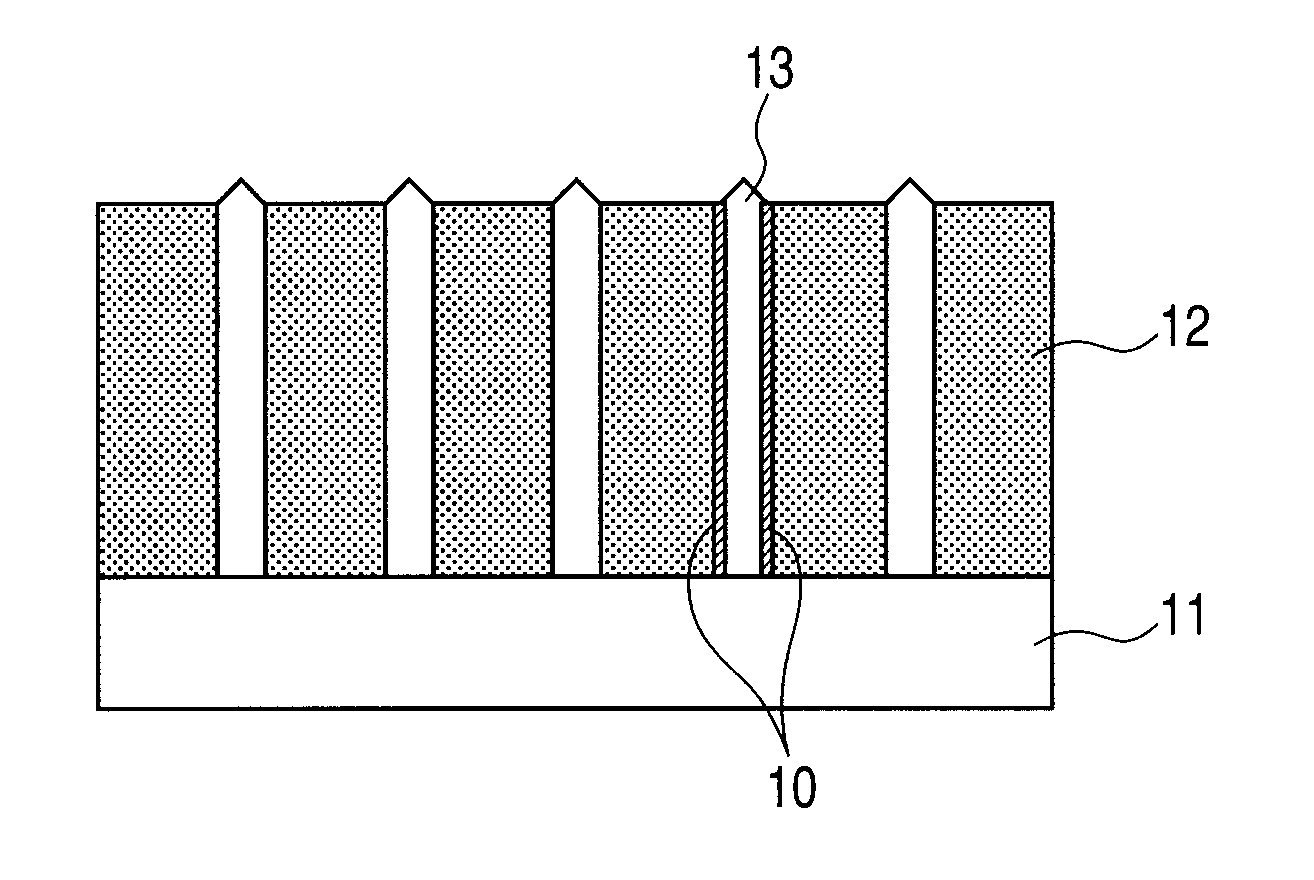
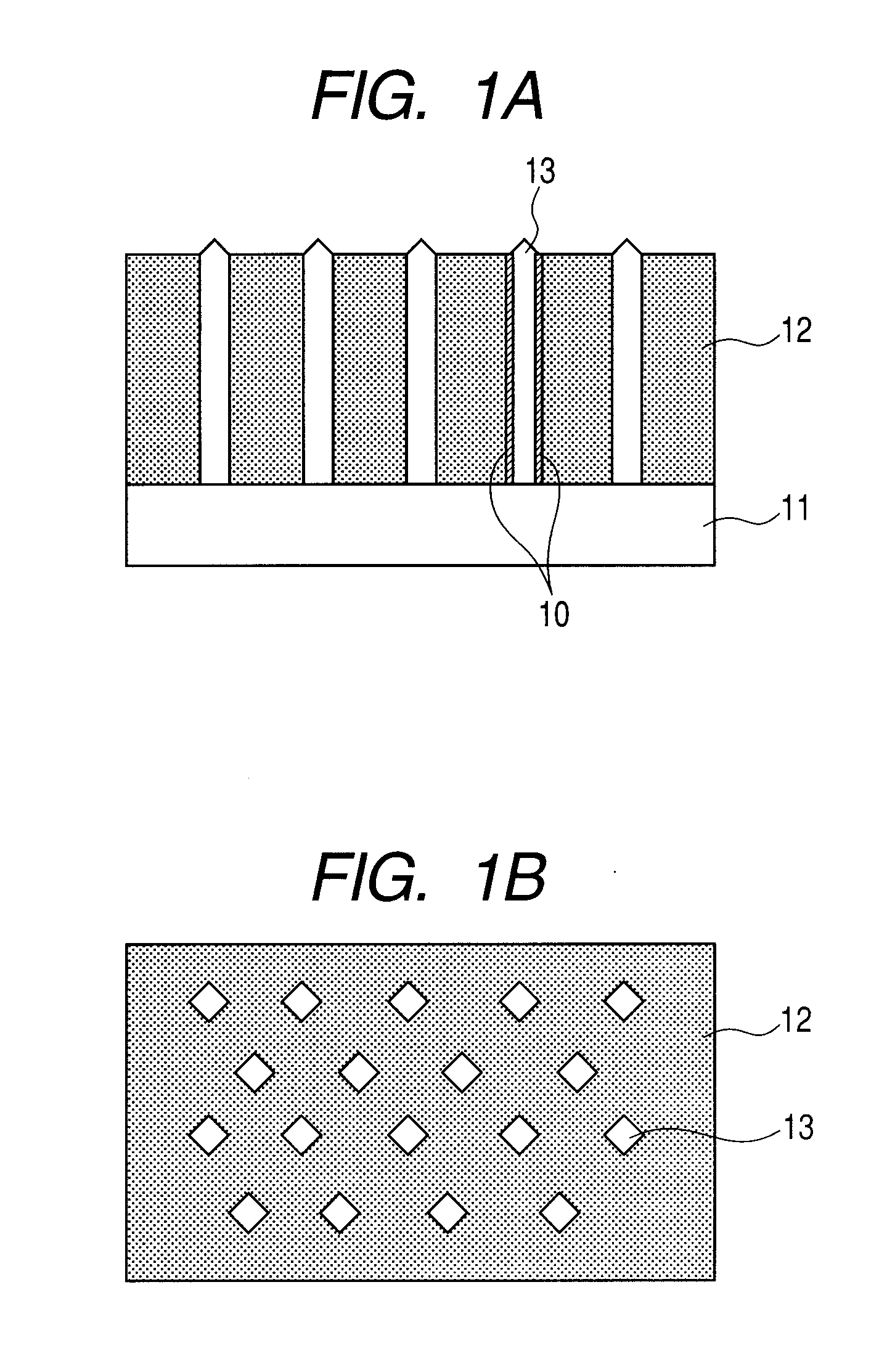
[0067]Description is given by using a ferroelectric thin film illustrated in each of FIGS. 1A and 1B.
[0068]The ferroelectric thin film 12 and the column group 13 formed of a spinel-type metal oxide are formed on the substrate 11 by a sputtering method. (100)La—SrTiO3 is used as the substrate 11. The ferroelectric thin film 12 and the column group 13 are formed by simultaneous progress of film deposition and phase separation. Here, when a film deposition rate is small, the diameter of the column group becomes excessively large. In addition, the column group grows, which has a (111) plane as a surface, because that is stable plane in a spinel type structure. In view of the foregoing, in order that the film deposition rate may be increased, the film deposition is performed while an oxygen partial pressure is increased.
[0069]A green compact target was used as...
example 2
[0082]A BiFeO3 ferroelectric film containing a column group with CoFe2O4 composition and having a thickness of 200 nm to 300 nm as Example 2 was produced in the same manner as in Example 1 except that the composition of the green compact target was changed to “Bi2O3:Fe2O3:Co3O4=(110 to 140):80:20” in terms of a molar ratio. The column group was evaluated from a sectional TEM image (lattice image) and an FFT image in the same manner as in Example 1.
[0083]As a result, it was confirmed that the column group and the ferroelectric thin film contact each other at a (110) surface, that is, a (hk0) plane. Further, it was confirmed that the ferroelectric thin film and the column group are oriented at (001) plane by representation of pseudo-cubic. An average circle-equivalent diameter of the column group was about 14 nm and a surface density of the column group was about 5.0×10¹⁴ columns / m2.
PUM
 Abstract
Description
Claims
Application Information
 - R&D Engineer
- R&D Manager
- IP Professional
- Industry Leading Data Capabilities
- Powerful AI technology
- Patent DNA Extraction
Browse by: Latest US Patents, China's latest patents, Technical Efficacy Thesaurus, Application Domain, Technology Topic, Popular Technical Reports.
© 2024 PatSnap. All rights reserved.Legal|Privacy policy|Modern Slavery Act Transparency Statement|Sitemap|About US| Contact US: help@patsnap.com