Spindle device for machine tool

a machine tool and spindle technology, applied in the direction of attachable milling devices, manufacturing tools, mechanical equipment, etc., can solve the problems of difficult to suppress the generation of vibrations, difficult to appropriately change the machining conditions, and difficult to greatly change the generation limit of regenerative chatter, etc., to reduce the generation of chattering during machining, increase the cut amount per unit time, and reduce the effect of vibration generation

Inactive Publication Date: 2011-04-07
JTEKT CORP
View PDF6 Cites 22 Cited by
  • Summary
  • Abstract
  • Description
  • Claims
  • Application Information

AI Technical Summary

Benefits of technology

[0011]According to another feature of an example of the invention, in addition to the damping force that is applied by the damping application means, a preload that is applied by preload application means is controlled based on, for example, the type of the tool. Therefore, it is possible to adjust the stiffness of a front rolling bearing in addition to the damping property of the rear rolling bearing. Therefore, it is possible to suppress the generation of chattering during machining performed using various tools. As a result, it is possible to increase the cut amount per unit time to increase the productivity.
[0012]According to a further feature of an example of the invention, a hydrostatic bearing is provided as the damping application means. Therefore, it is possible to execute controls with high accuracy. As a result, it is possible to suppress the generation of chattering during machining performed using various tools.
[0013]According to another feature of the invention, by way of example, a pressure ratio of the hydrostatic bearing and a supply hydraulic pressure are co

Problems solved by technology

In addition, this relationship varies depending on the degree of deterioration, for example, abrasion of the tool.
Accordingly, it is not easy to appropriately change the machining conditions.
Therefore, it is difficult to greatly change the generation limit of the regenerative chatter by just changing the stiffness, and a damping property needs to be pr

Method used


Image

  • Spindle device for machine tool
  • Spindle device for machine tool
  • Spindle device for machine tool

Examples


Embodiment Construction

[0027]Hereinafter, embodiments of the invention will be described with reference to the accompanying drawings.

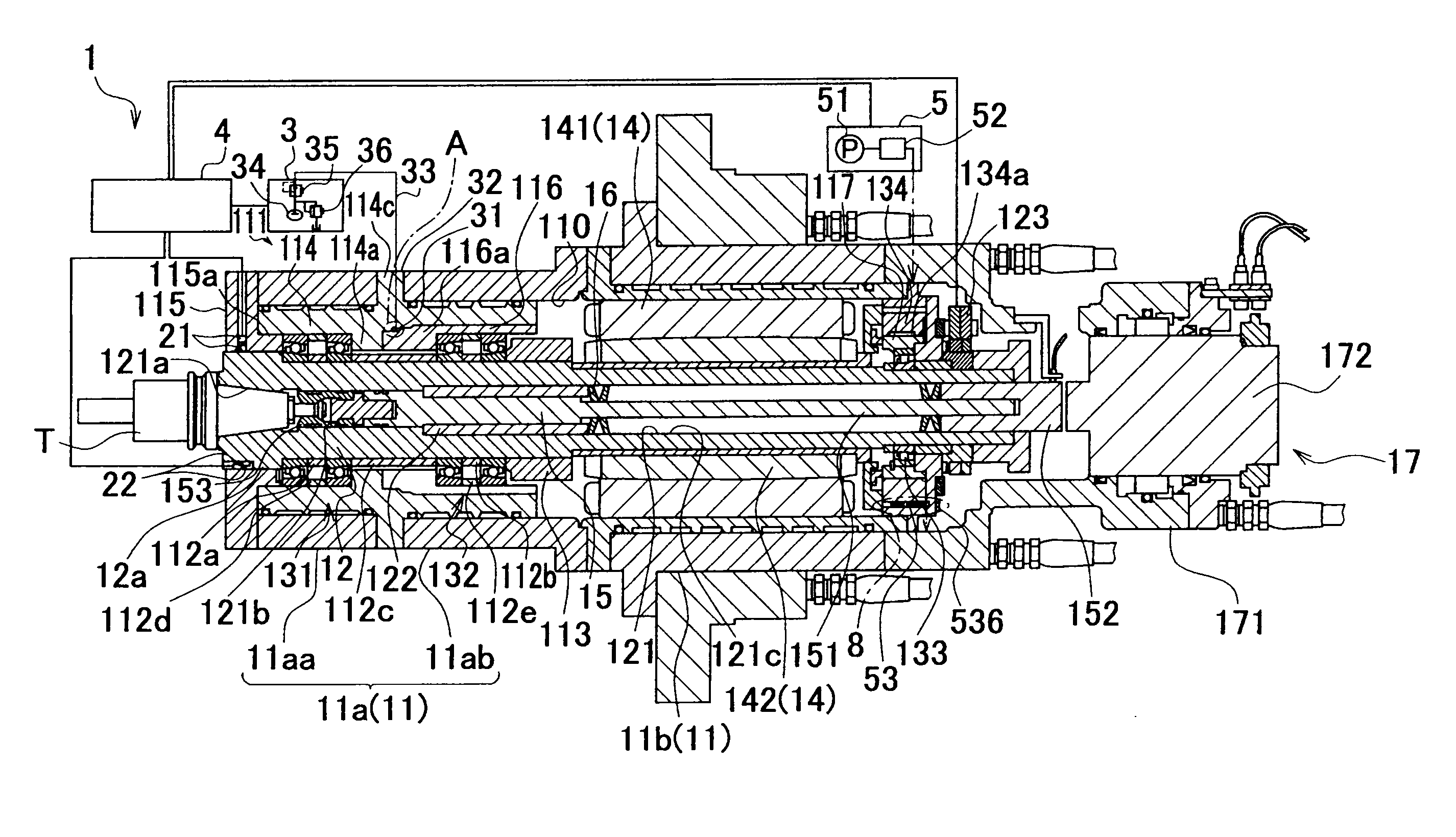
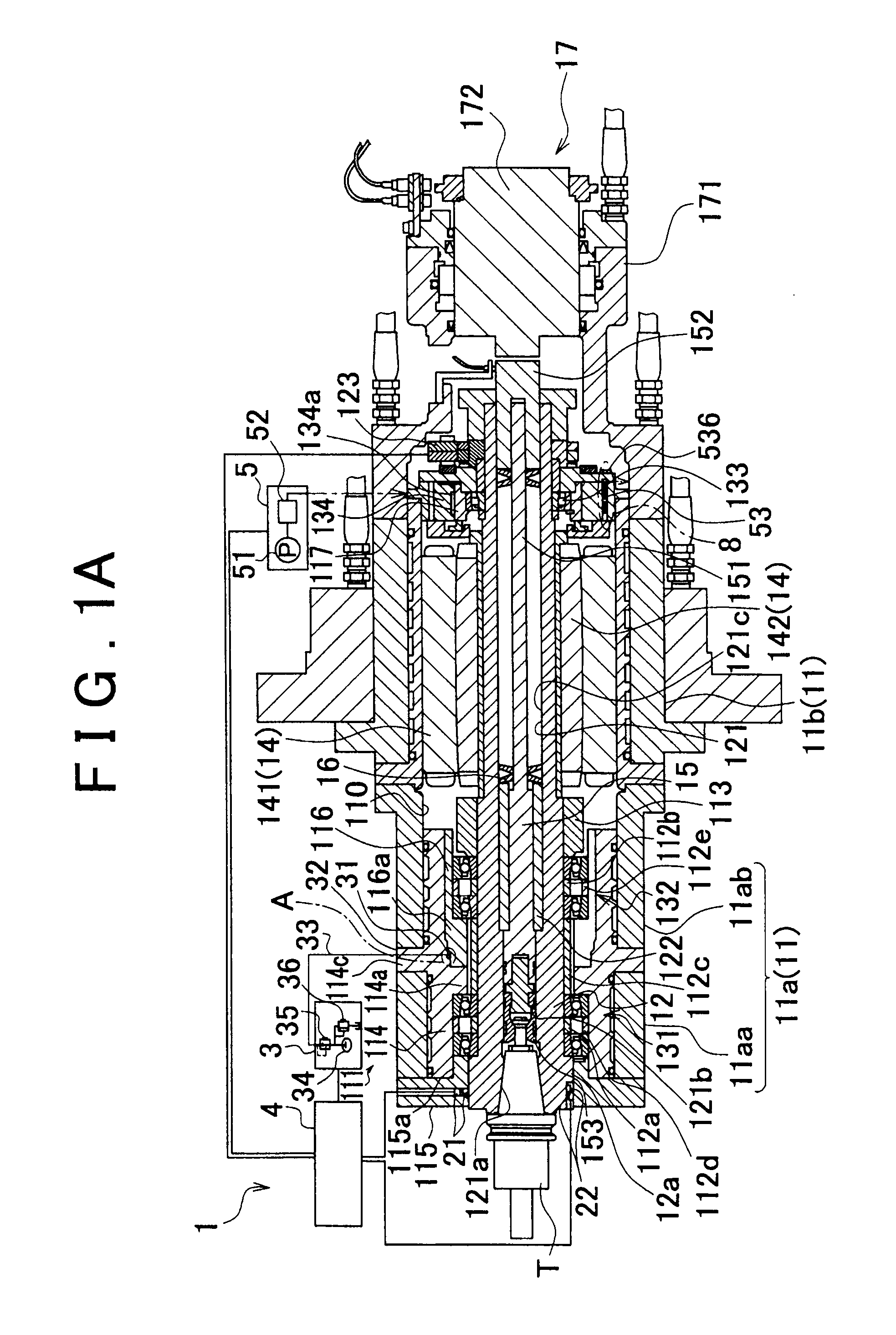
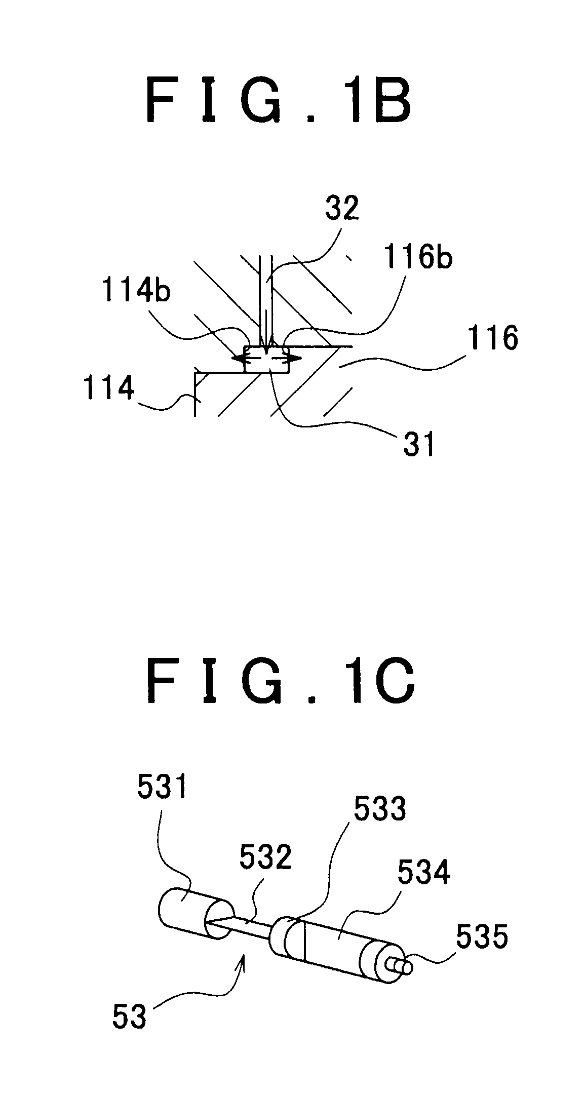
[0028]FIG. 1(A) is a longitudinal sectional view that shows the overall structure of a spindle device 1 according to an embodiment of the invention. FIG. 1(B) is an enlarged sectional view of a portion A shown in FIG. 1(A). FIG. 2 is a block diagram of a control unit of the spindle device 1 in FIG. 1(A). Note that, in FIG. 1(A), the lateral direction is an axial direction, and the left side is defined as a front side. As shown in FIG. 1(A), the spindle device 1 according to the present embodiment includes a substantially cylindrical spindle housing 11, a spindle 12, a pair of first front rolling bearings 131, a pair of second front rolling bearings 132 and a rear rolling bearing 133. The spindle housing 11 has an accommodating space 110 inside its inner peripheral portion. The spindle 12 is arranged in the accommodating space 110. The pair of first front rolling bearings 131...


PUM

PropertyMeasurementUnit
Timeaaaaaaaaaa
Pressureaaaaaaaaaa
Ratioaaaaaaaaaa

Abstract

The damping property of a rear rolling bearing (133) is adjusted by controlling a damping force that is applied by damping application means (5, 134) based on, for example, the type of a tool (T). Thus, it is possible to provide the optimum damping properties for various tools that differ in natural vibration, and to suppress the generation of chattering of the various tools. As a result, it is possible to increase the cut amount per unit time to increase the productivity.

Description

INCORPORATION BY REFERENCE[0001]This application claims priority to Japanese Patent Application No. 2009-232290 filed on Oct. 6, 2009, the disclosure of which, including the specification, drawings and abstract, is incorporated herein by reference in its entirety.BACKGROUND OF THE INVENTION[0002]1. Field of the Invention[0003]The invention relates to a spindle device used for, for example, a machine tool.[0004]2. Description of the Related Art[0005]A spindle of a spindle device for a machine tool is supported by rolling bearings having high stiffness and high precision in order to increase productivity. However, for example, in a machining center, workpieces are machined with the use of various tools such as a milling cutter, an endmill and a boring tool. Therefore, generated cutting resistance varies depending on the tools. Further, many factors such as stiffness and weights of tools, rotation speeds of spindles, feedrates and feed amounts (hereinafter, referred also to as “depths ...

Claims


Application Information

Patent Timeline
IPC IPC(8): B23Q5/04
CPCB23Q1/265B23Q1/70B23Q11/0039B23Q17/0976Y10T409/309464Y10T409/304312Y10T408/76Y10T409/309352F16C25/083
Inventor OGURA, KAZUNARIHORI, NOBUMITSUNAKASHIMA, KUNIMICHIOKAWA, YUJISHIBATA, TAKAMASA
Owner JTEKT CORP
Why Eureka
Try Eureka