Method and Apparatus For Achieving Higher Thermal Efficiency In A Steam Engine or Steam Expander

Active Publication Date: 2011-04-14
THERMAL POWER RECOVERY
View PDF98 Cites 21 Cited by
  • Summary
  • Abstract
  • Description
  • Claims
  • Application Information

AI Technical Summary

Benefits of technology

[0006]In view of these and other shortcomings of the prior art it is the general object of the invention is to provide a new Rankine (steam) operating cycle that provides an extraordinary improvement in overall operating efficiency for a steam engine or expander enabling them to become competitive with the internal combustion engine in some vehicular applications.
[0007]Another object is to provide a steam engine expander for efficiently recovering waste heat energy from an internal combustion engine which typically wastes about two-thirds to three-fourths of the heat in the fuel that is consumed, thereby providing the prospect of an enormous saving in U.S. fuel imports which now amount to 9.667 million barrels per day (2009).
[0008]A more specific object is to provide a new steam operating cycle for a steam engine or steam expander that is substantially more efficient than the most efficient k

Problems solved by technology

In spite of the far superior exhaust emission characteristics of a steam engine and its ability to use a variety of fuels includin

Method used


Image

  • Method and Apparatus For Achieving Higher Thermal Efficiency In A Steam Engine or Steam Expander
  • Method and Apparatus For Achieving Higher Thermal Efficiency In A Steam Engine or Steam Expander
  • Method and Apparatus For Achieving Higher Thermal Efficiency In A Steam Engine or Steam Expander

Examples


Embodiment Construction

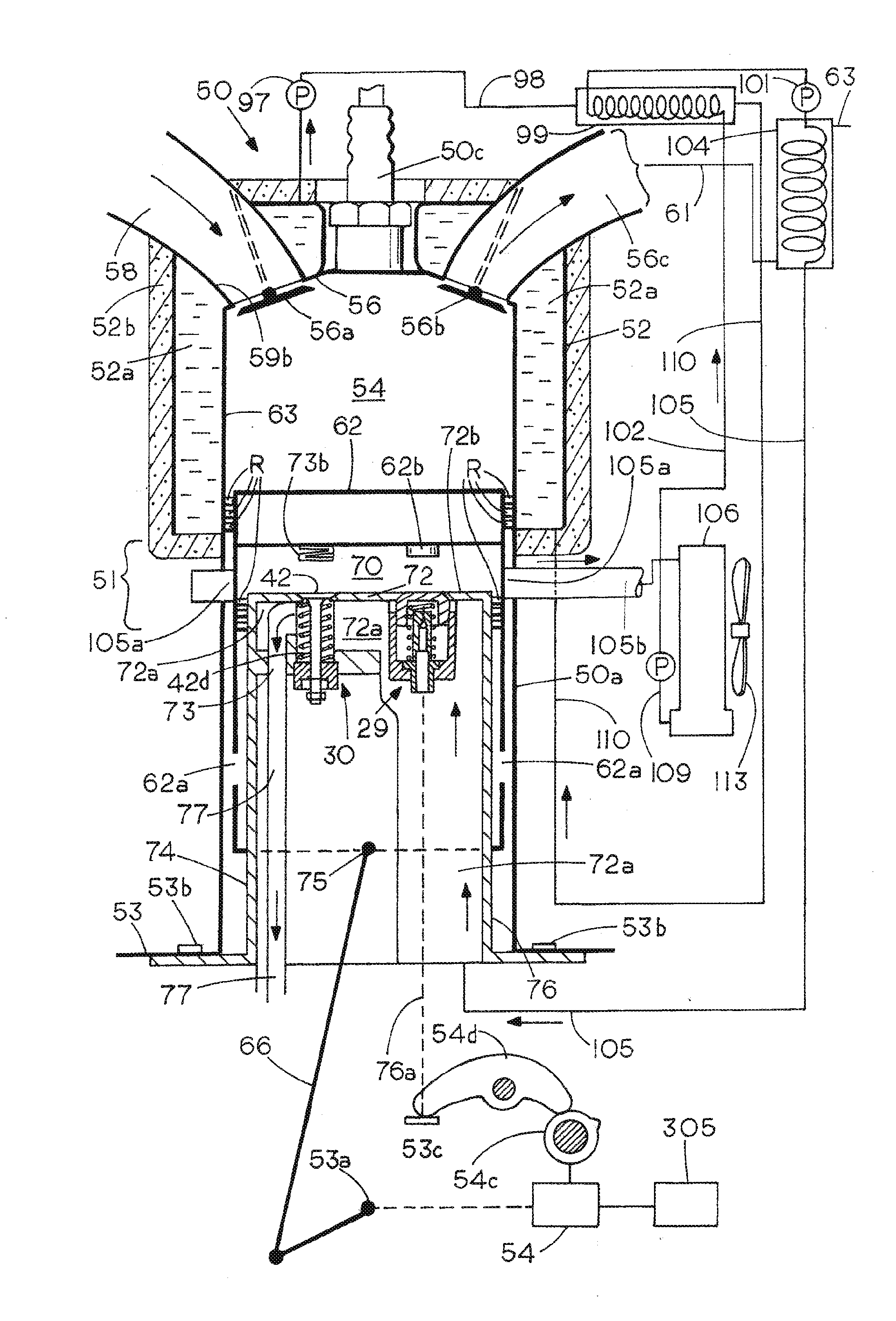
[0032]Steam engines currently available are represented by one of two design philosophies; counterflow or uniflow. The counterflow philosophy exemplified by the steam locomotive is based upon increasing work output by having compression work low at the expense of adding a generous portion of clearance between the piston and cylinder head at the end of the return stroke. The uniflow philosophy introduced in about 1907 and improved during the 1940's by Calvin Williams (U.S. Pat. Nos. 2,402,699 and 2,943,608) increased efficiency considerably over counterflow by lowering fuel energy input at the expense of substantial compression work. The compression of residual steam within the cylinder to throttle pressure allowed the engine to add heat to the cylinder and prevented a pressure drop as steam was injected at the beginning of the next power stroke.

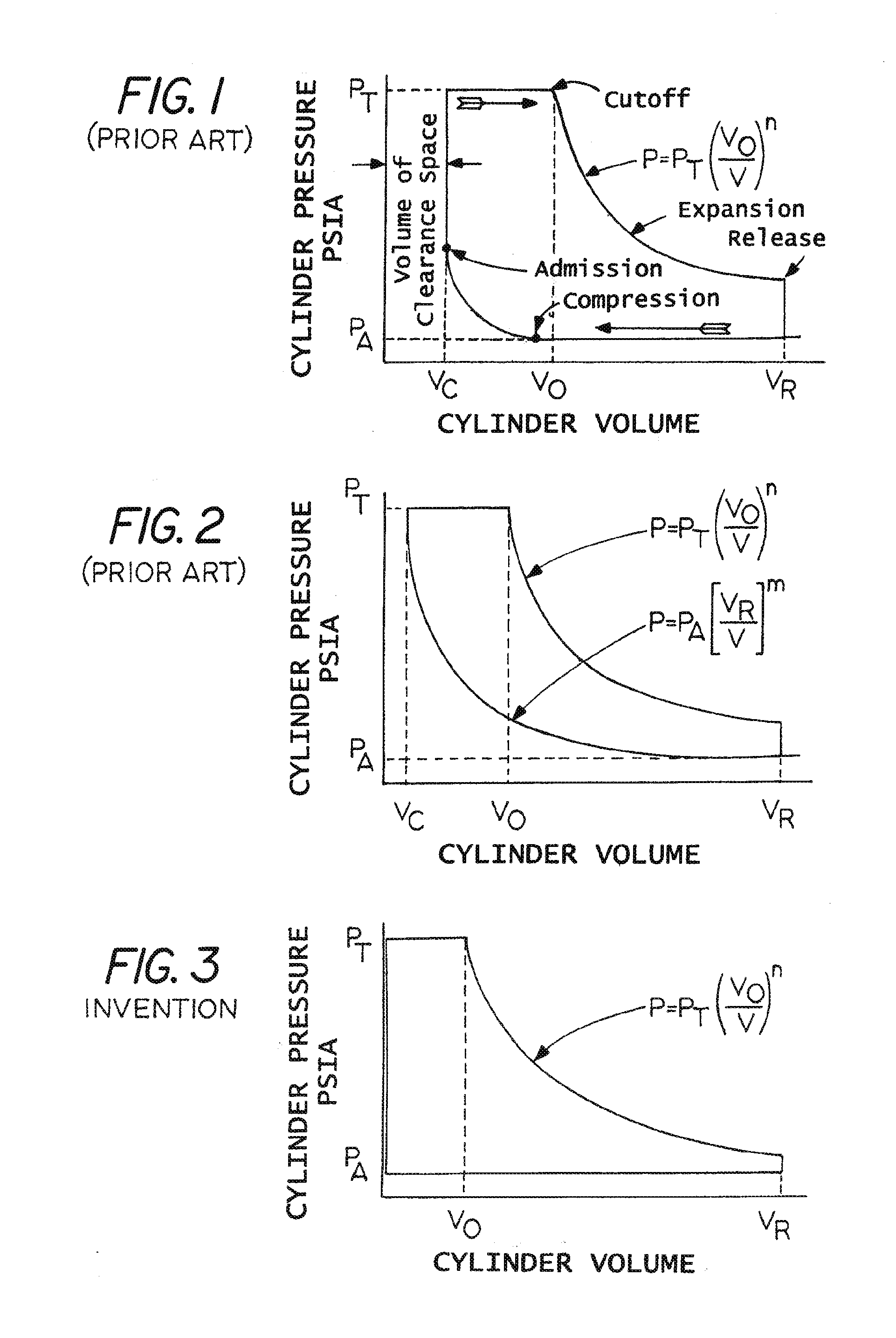
[0033]A better understanding of the invention can be gained through a comparison of mathematical equations for Rankine cycles that describe ...


PUM


Abstract

A high order of thermal efficiency is achieved in a steam engine or expander having a piston clearance that approximates zero together with a negligible amount of compression, such that pressure in the clearance volume approximates ambient pressure, i.e. atmospheric or condenser pressure as the case may be at the end of the piston return stroke when the clearance is essentially zero. These two provisions working together simultaneously provide a method and apparatus which constitute a new engine apparatus and Rankine operating cycle that can be referred to as “zero clearance with zero compression”. The invention also provides an improved steam admission valve assembly that can be operated either automatically responsive to piston movement or by means of a cam shaft and cam or electrically by means of a solenoid that provides an intermittent magnetic field for operating one or more valves. A biphasic exhaust system is described in which a piston operated valve opens to exhaust steam in a primary phase at or near maximum displacement, and in a secondary phase an auxiliary, normally open exhaust valve facing the top of the piston permits virtually all residual steam to be exhausted through the approximate end of the piston return stroke after which it is closed by the piston, by a lifter on the piston or by the cam and finally held closed during the power stroke by a fresh charge of steam injected through the steam admission valve into the clearance volume as it approaches zero.

Description

DEPENDENCY FROM OTHER APPLICATIONS[0001]The present application is a continuation-in-part of application Ser. No. 12 / 539,987, filed Aug. 12, 2009, which in turn is a continuation-in-part of application Ser. No. 12 / 492,773, filed Jun. 26, 2009 (now abandoned), a continuation-in-part of copending application Ser. No. 12 / 844,607, filed Jul. 27, 2010, a continuation-in-part of Ser. No. 12 / 387,113, filed Apr. 28, 2009 and Ser. No. 12 / 075,042, filed Mar. 7, 2008.[0002]The applicants also the benefit of the following provisional applications: 61 / 039,640, filed Mar. 2, 2010; and 61 / 320,959, filed Apr. 5, 2010; and 60 / 905,732, filed Mar. 7, 2007, all of which are incorporated herein by reference.FIELD OF THE INVENTION[0003]This invention relates to steam engines as well as steam expanders that can be used as a part of a dual cycle engine, and especially to a method and apparatus for achieving higher efficiency in such engines and expanders.BACKGROUND OF THE INVENTION[0004]Steam engines which...

Claims


Application Information

Patent Timeline
IPC IPC(8): F01K23/10F01B29/06
CPCF01B7/20F01B17/04F01B21/02Y02T10/16F02B75/30Y02T10/14F02B41/00Y02T10/12
Inventor PEOPLES, JERRY A.HARMON, SR., JAMES V.
Owner THERMAL POWER RECOVERY
Why Eureka
Try Eureka