Device and method for harvesting energy from flow-induced oscillations

a technology of flow-induced oscillation and energy harvesting device, which is applied in the direction of electric generator control, machines/engines, sustainable buildings, etc., can solve the problems of inefficiency in energy conversion, oscillation onset, source of instability, etc., and achieve the effect of maximum energy conversion efficiency

Inactive Publication Date: 2011-04-14
KAPLAN A MORRIS
View PDF38 Cites 4 Cited by
  • Summary
  • Abstract
  • Description
  • Claims
  • Application Information

AI Technical Summary

Benefits of technology

[0025]The configuration of each vibrating assembly of each device of the system o

Problems solved by technology

Although the turbine-based wind generators are, in general, effective in certain conditions, they have limitations resulting from typical requirements of large open spaces (consistently high-speed winds), infrastructure development requirements and large initial capital costs.
While such generators can provide sufficient energy for small applications, they are not optimized for efficient conversion of energy available in various flows of gases or fluids.
This mass requires a special vibrating assembly and, in some cases, a source of instability at the oscillation onset.
This limits the span of possible oscillation frequencies and/or may damp down the desired oscillation frequencies for certain flow characteristics.
Moreover, in

Method used


Image

  • Device and method for harvesting energy from flow-induced oscillations
  • Device and method for harvesting energy from flow-induced oscillations
  • Device and method for harvesting energy from flow-induced oscillations

Examples


example

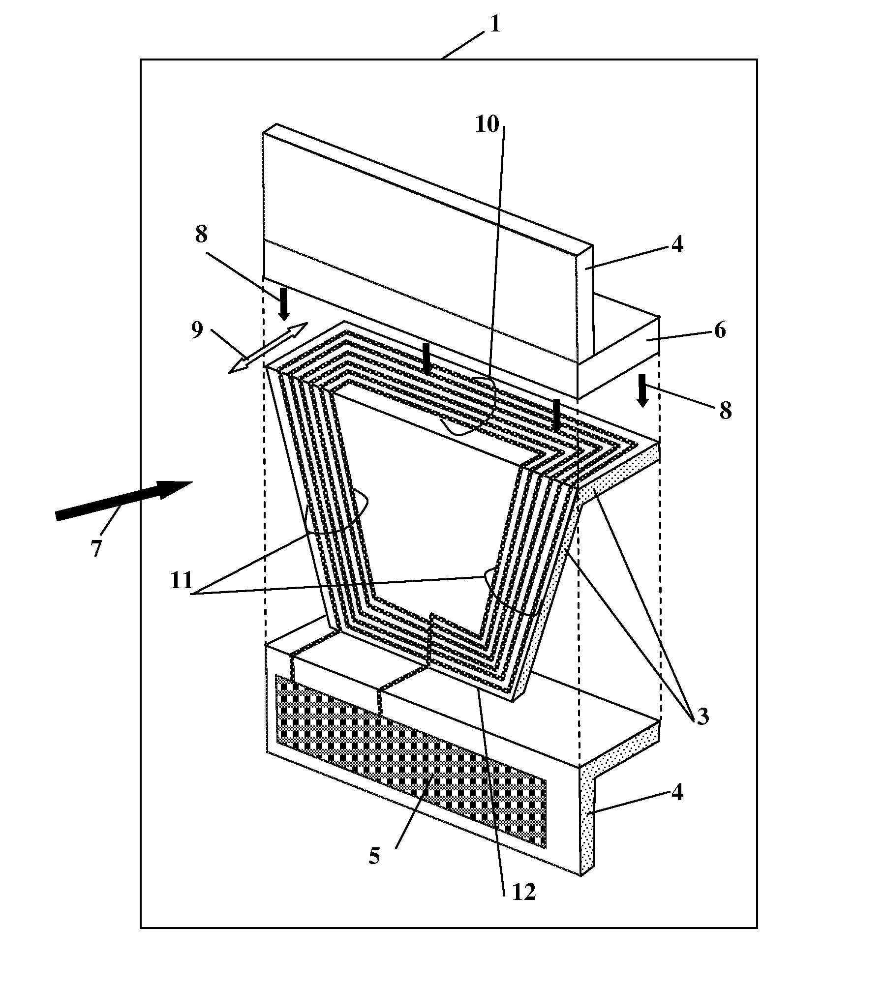
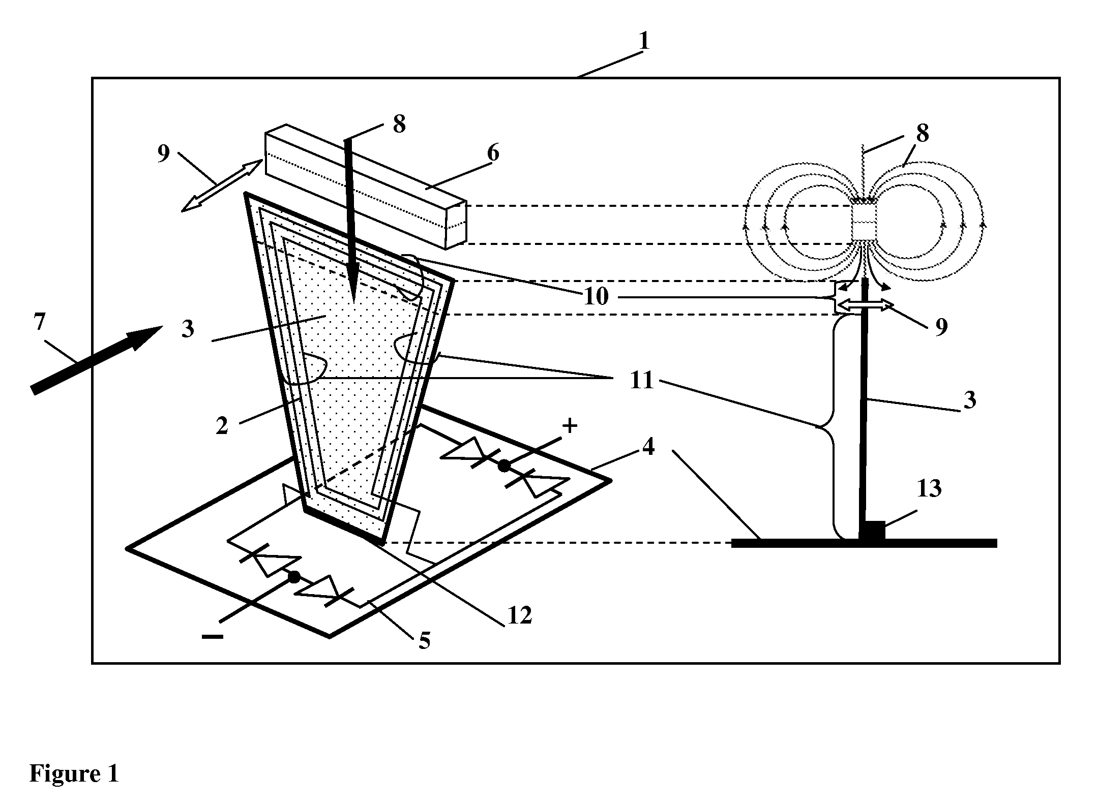
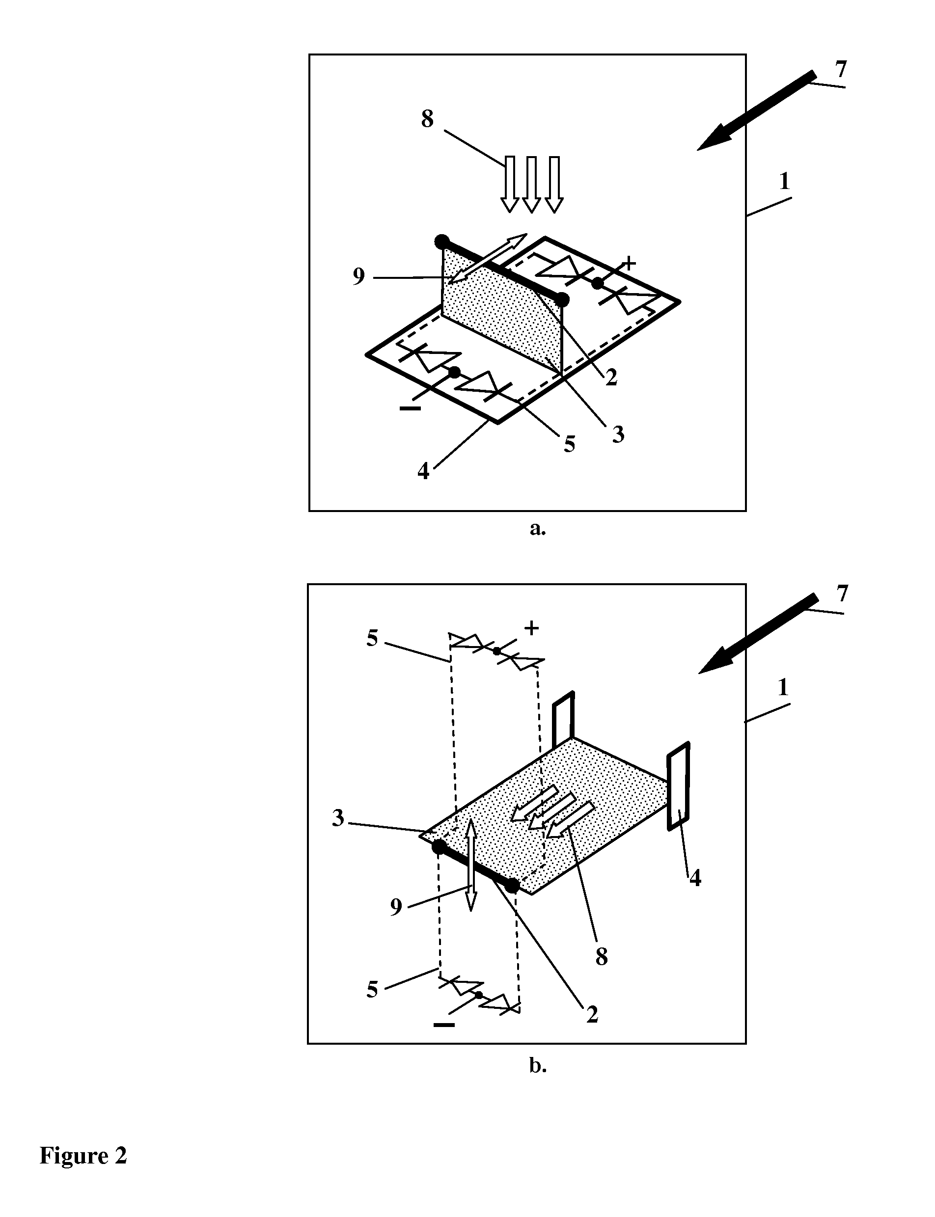
[0092]Exemplary experimental characteristics of the configuration of the generating cell of the present teachings for flow velocities between about 2 m / c and about 10 m / c are as follows.

[0093]The size of the elongated thin elastic plate is between about 30 mm and about 80 mm in length, and is about 5 mm in width; the mass of the elastic plate is about 10−3 kg; the frequency of the fundamental vibration mode is between about 20 Hz and about 150 Hz; the vibration amplitude is between about 0.5 mm and about 2 mm.

[0094]The experiments were conducted in such a way that the characteristic frequencies of the turbulent flow in the experimental setup were substantially equal, within an order of magnitude or less, to the fundamental vibration mode frequencies (or a combination thereof) of the vibrating assembly. This condition is preferred for the maximum flow energy capture efficiency.

[0095]FIG. 5a illustrates the time dependence of the oscillation amplitude of the experimental device compri...


PUM


Abstract

A device and method utilizing a quasi-stationary oscillating process to generate electricity by using an interaction between a turbulent flow and an elastic oscillating structure comprising a conductor in the presence of a magnetic field, followed by rectification of thus generated electromotive force, and a combination of similar independent multiple oscillating structures into a connected grid. An arbitrary number of adjustable generating cells can be connected into a single circuit, either in-series or in-parallel, to increase an overall power output. The disclosure is capable to operate under wide range of flow characteristics and can serve as a source of renewable power.

Description

CROSS REFERENCE TO RELATED APPLICATIONS[0001]This application is a continuation-in-part of a U.S. application Ser. No. 12 / 577,392 entitled “Apparatus for Harvesting Energy from Flow-Induced Oscillations and Method for the Same”, filed on Oct. 12, 2009, the entire content of which is incorporated by reference herein.FIELD OF INVENTION[0002]This invention relates to electricity generation from oscillations of a structure in the presence of a flow of a variety of types.BACKGROUND OF INVENTION[0003]The present teachings are related to the conversion of kinetic energy existing in various flows, such as an airflow, a water flow, a tidal wave, etc., into electricity. The present teachings describe a novel energy converter, and its various embodiments, that efficiently utilizes oscillations induced by different types of flow, in order to generate electricity.[0004]Mankind has been utilizing the flow energy of water or wind for centuries. The kinetic energy of a flow can be converted into ro...

Claims


Application Information

Patent Timeline
IPC IPC(8): F03D5/06F03D9/00
CPCF05B2250/41Y02E10/28Y02E10/70Y02E10/725F03B17/06F03B13/182F03G7/08F05B2210/16Y02B10/30Y02B10/70Y02E10/38F03D5/06Y02E10/30Y02E10/20Y02E10/72
Inventor KAPLAN, A. MORRIS
Owner KAPLAN A MORRIS
Why Eureka
Try Eureka