
Methods, systems and apparatus for dynamically controlling an electric motor that drives an oil pump

Active Publication Date: 2011-04-14
GM GLOBAL TECH OPERATIONS LLC
View PDF8 Cites 75 Cited by
  • Summary
  • Abstract
  • Description
  • Claims
  • Application Information

AI Technical Summary

Benefits of technology

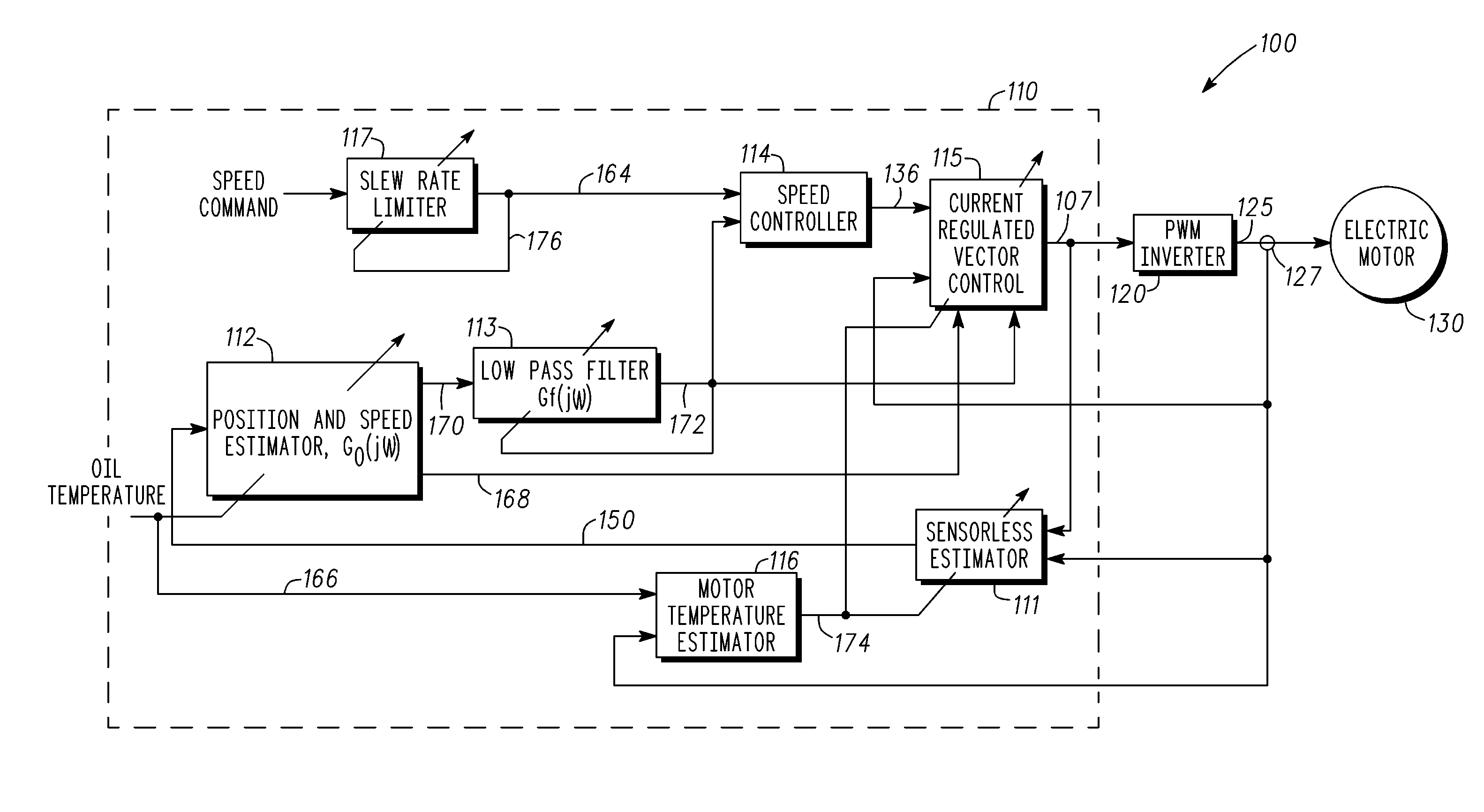
[0018]Embodiments of the present invention relate to methods, systems and apparatus for sensorless control that can b

Problems solved by technology

A speed or position sensor is an expensive component.
These sensors typically increase the cost and reliability of the motor drive system due to the fact that extra sensor components and additional wiring are required.
Moreover, the circuitry required to process its signals can also be expensive.
These sensors can also have reliability and maintenance issues.
The presence of the speed / position sensor in the system adds cost, size, and weight, and reduces reliability as well.
Although it would be desirable to use a PM motor and vector controlled motor drive system that uses sensorless control techniques to drive an oil pump, there are a number of considerations that make this quite challenging.
For example, when the oil being pumped gets cold, its viscosity increases (e.g., becomes slushy) and the load dynamics of the motor become relatively slow in comparison to when the oil is at a higher temperature.
At high temperatures, however, the oil becomes thin, and the load dynamics become relatively fast.
By contrast, when the oil is hot, the oil pump driven by the electric motor has to be robust to this load variations, which becomes an issue for sensorless control.
However, when the speed command changes too abruptly, it will create the sudden back pressure which makes the motor stop momentarily, or may even spin the motor backward for a short time.
When the actual motor speed changes too fast, this can induce control instability in sensorless control techniques that have finite bandwidth to estimate the rotor's position and angular velocity.
Dynamic performance of the sensorless control techniques described in the published applications mentioned above can be somewhat limited.
For example, at higher bandwidths and motor speeds, a rotor position and speed estimator can track / estimate the position and speed of the rotor relatively well, but can exhibit control instability due to the noise.
Nevertheless, the system may exhibit control instability when dynamic variation of the load changes too rapidly.

Method used


Image

  • Methods, systems and apparatus for dynamically controlling an electric motor that drives an oil pump
  • Methods, systems and apparatus for dynamically controlling an electric motor that drives an oil pump
  • Methods, systems and apparatus for dynamically controlling an electric motor that drives an oil pump

Examples


Embodiment Construction

[0038]As used herein, the word “exemplary” means “serving as an example, instance, or illustration.” The following detailed description is merely exemplary in nature and is not intended to limit the invention or the application and uses of the invention. Any embodiment described herein as “exemplary” is not necessarily to be construed as preferred or advantageous over other embodiments. All of the embodiments described in this Detailed Description are exemplary embodiments provided to enable persons skilled in the art to make or use the invention and not to limit the scope of the invention which is defined by the claims. Furthermore, there is no intention to be bound by any expressed or implied theory presented in the preceding technical field, background, brief summary or the following detailed description.

[0039]Overview

[0040]Before describing in detail embodiments that are in accordance with the present invention, it should be observed that the embodiments reside primarily in comb...


PUM


Abstract

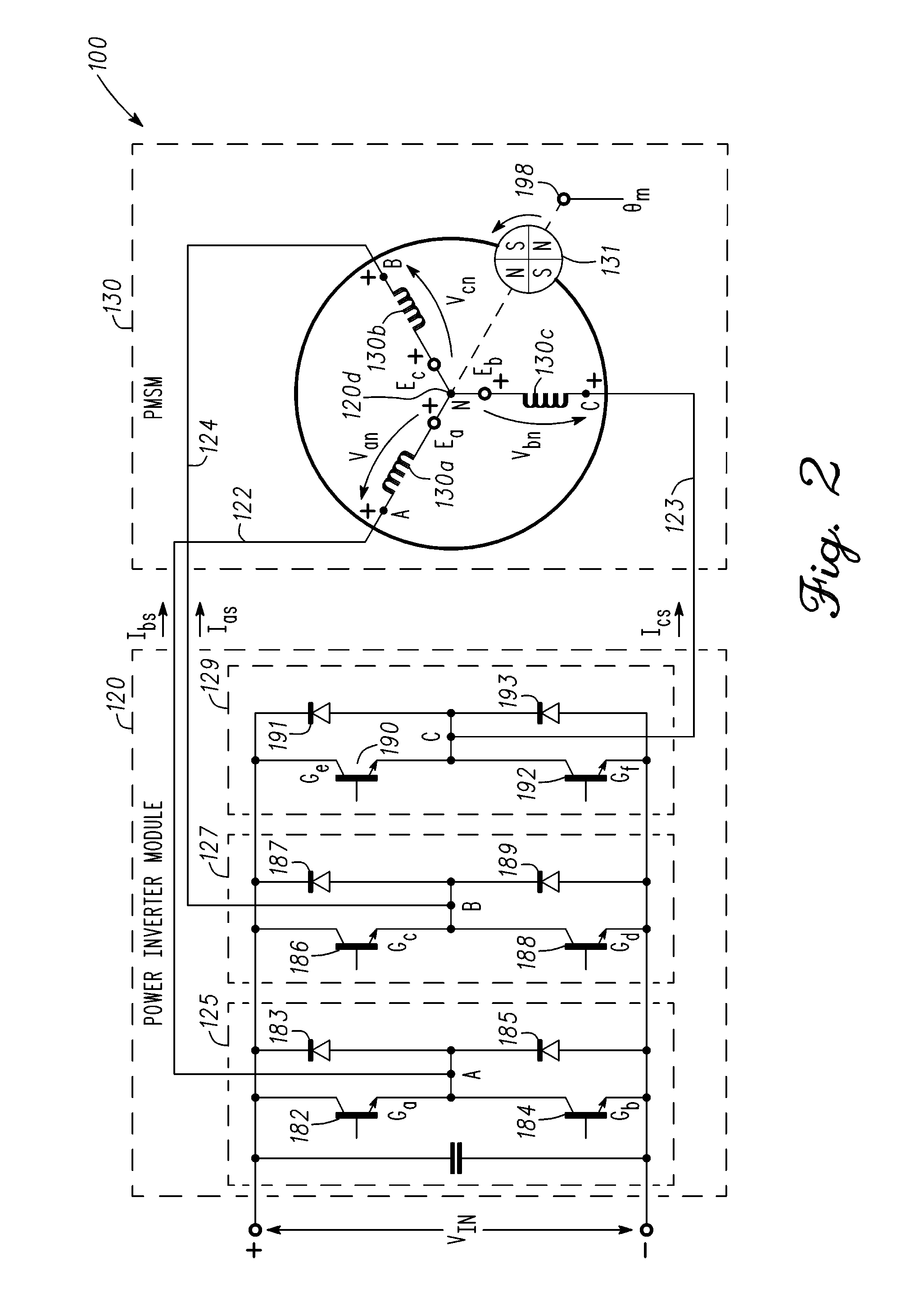
Methods, system and apparatus are provided for sensorless control of a vector controlled motor drive system that includes an electric motor used to drive an auxiliary oil pump.

Description

TECHNICAL FIELD[0001]The present invention generally relates to hybrid and electric vehicle power systems, and more particularly relates to techniques for enhancing motor control of an auxiliary oil pump to provide dynamic performance over a wide range of oil temperatures.BACKGROUND OF THE INVENTION[0002]Hybrid and electric vehicles (HEVs) typically include an electric traction drive system that includes an alternating current (AC) electric motor which is driven by a power converter with a direct current (DC) power source, such as a storage battery. Motor windings of the AC electric motor can be coupled to inverter sub-modules of a power inverter module (PIM). Each inverter sub-module includes a pair of switches that switch in a complementary manner to perform a rapid switching function to convert the DC power to AC power. This AC power drives the AC electric motor, which in turn drives a shaft of HEV's drivetrain. Traditional HEVs implement multiple three-phase pulse width modulate...

Claims


Application Information

Patent Timeline
IPC IPC(8): H02P6/18H02P6/08
CPCB60K1/02B60L1/003F04C14/08F04C18/00F04C2210/14F04C2270/0525Y10T477/23H02P6/085H02P6/18H02P29/0044Y02T10/642B60L2200/26Y10T477/653G05B11/28H02P21/00H02P29/60Y02T10/64
Inventor PATEL, NITINKUMAR R.SON, YO CHAN
Owner GM GLOBAL TECH OPERATIONS LLC
Learn More