
Offset pickup tines to improve feeding pick up

a technology of off-set pickups and rotors, which is applied in the field of pick-ups, can solve the problems of unfavorable crop control, unfavorable crop control, and plugging in the pickup and/or rotor, etc., and achieve the effects of reducing and/or substantially eliminating dead areas, improving crop control, and reducing dead areas

Active Publication Date: 2011-04-21
BLUE LEAF I P INC
View PDF33 Cites 9 Cited by
  • Summary
  • Abstract
  • Description
  • Claims
  • Application Information

AI Technical Summary

Benefits of technology

Embodiments of the present invention address and overcome one or more of the above shortcomings and drawbacks, by providing offset mounted pickup tines that reduce and / or substantially eliminate the dead area between the pickup tines and the rotor. This reduced dead area when the pickup is in the transfer position provides improved control of the crop as it is transferred from the pickup to a downstream member of the machinery feeder assembly. Embodiments of the offset pickup tines may be used for crop or forage pickup machinery.
According to another aspect of the invention, the offset mounting of the pickup tines brings the pickup rotor tines in close proximity to a rotor downstream of the pickup in the crop flow to reduce a dead area between the pickup and the rotor.
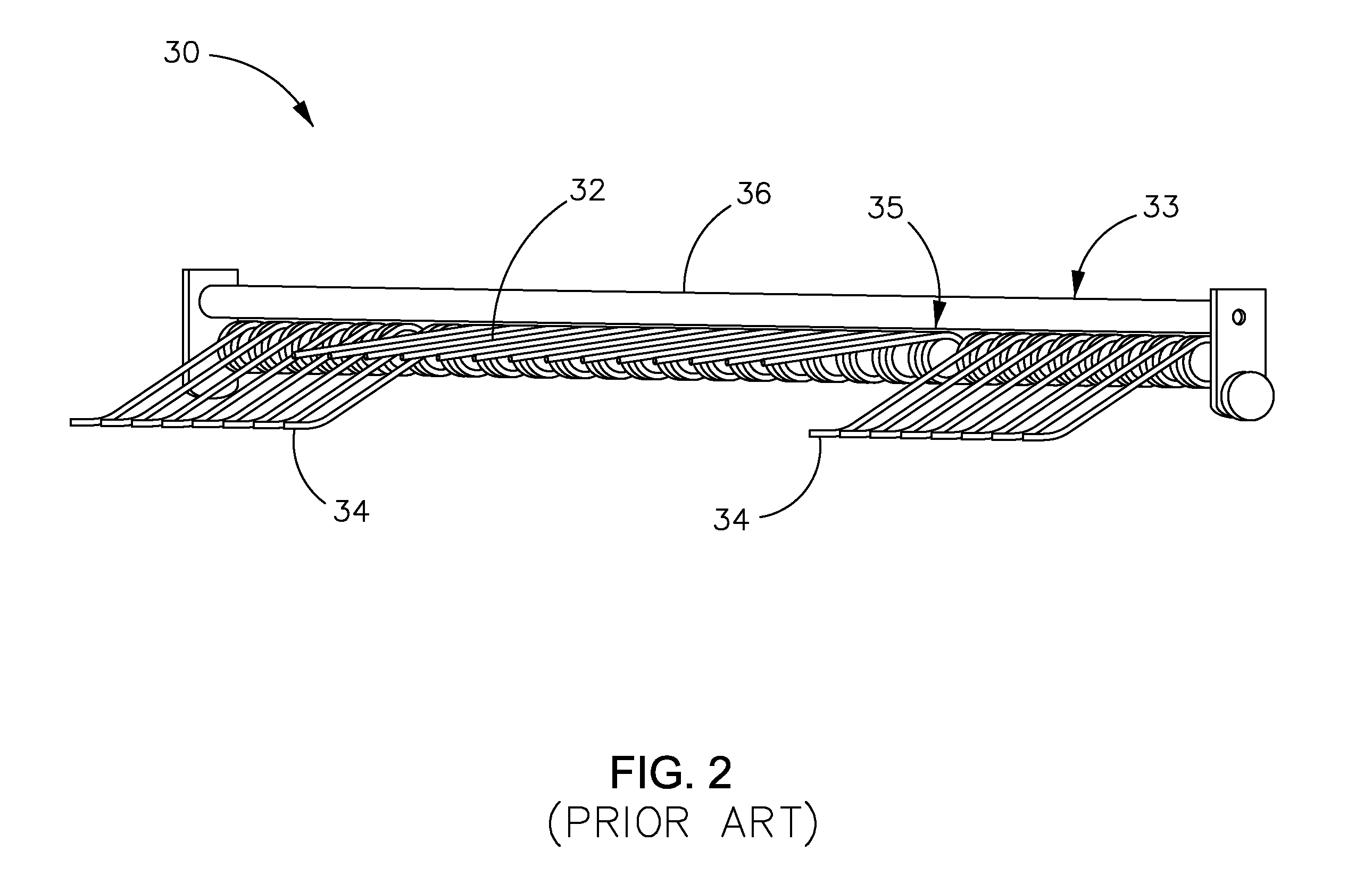
According to another aspect of the invention, the pickup mechanism further includes a pickup position and a transfer position. In the transfer position: the pickup auger tines are in close proximity to augers positioned downstream of the pickup mechanism in a feeder assembly, and the pickup rotor tines are in close proximity to tines of the rotor positioned downstream of the pickup mechanism in the feeder assembly. The positioning of the pickup rotor tines on the leading edge of the tine bar reduces any dead area between the pickup rotor tines and tines of the rotor.
According to still other embodiments of the invention, an improved pickup mechanism is provided for use, for example, with a feeder assembly of a baler or crop harvester. The pick-up mechanism includes a pickup weld assembly or housing having a feed opening. A plurality of tine bars extend transversely across the pickup weld assembly. Each tine bar comprises a longitudinal length and axis of rotation, a central portion, two end portions, a leading edge, and a trailing edge. An off-set mounting of the pickup tines to the tine bar is provided. The offset mounting comprising: a plurality of elongate spaced-apart auger tines connected to a trailing edge of each of the pickup tine bars at the end portions, the auger tines extending outward from the tine bars; and a plurality of elongate spaced-apart rotor tines connected to a leading edge of each of the pickup tine bars at the central portion, the rotor tines extending outward from the tine bars. A rotor may be positioned downstream to the pickup tine bars, the rotor being spaced apart from said pickup tine bar and defining a space therebetween. A pickup drive shaft may be operatively coupled to the pickup tine bars via, for example, a cam assembly. The tine bars may be driven by and rotate about the pickup drive shaft and the cam assembly may cause rotation of the tine bars about the tine bar axis of rotation. A transfer position exists wherein the pickup rotor tines of one of the tine bars are in close proximity to the rotor in the center of the pickup weld assembly and the pickup auger tines of the same tine bar are in close proximity to augers at the ends of the pickup weld assembly. The offset mounting of the pickup tines resulting in improved crop control as the crop is transferred from the pickup to the rotor due to a reduced dead area between the pickup and the rotor.

Problems solved by technology

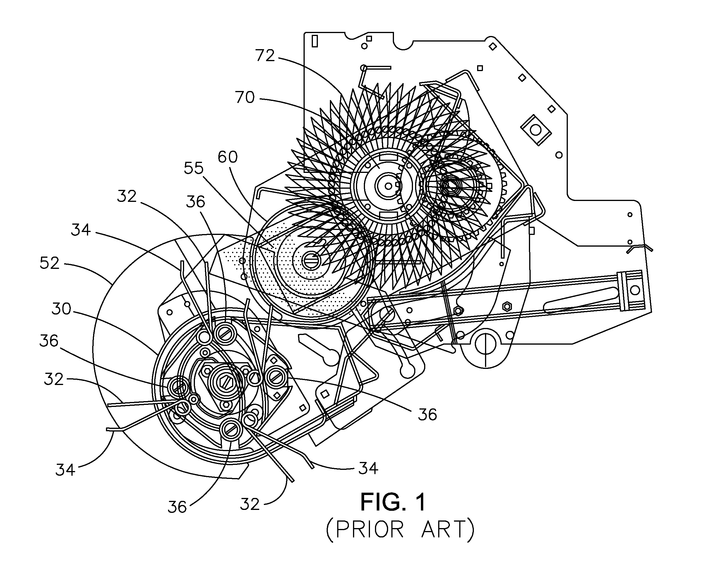
The configuration results in an undesirerable space or “dead area” where crop can lie without being contacted by either the pickup tines or the rotor (see e.g., FIG. 1).
As a result, this area can fill up with crop material and cause plugs in the pickup and / or rotor.
This may be especially problematic for light crop.
While this does reduce the “dead area” slightly, it is not sufficient to eliminate the problem.
Also, modification of the rotor tines requires two different tine designs, resulting in manufacturing, inventory and maintenance issues.

Method used


Image

  • Offset pickup tines to improve feeding pick up
  • Offset pickup tines to improve feeding pick up
  • Offset pickup tines to improve feeding pick up

Examples


Embodiment Construction

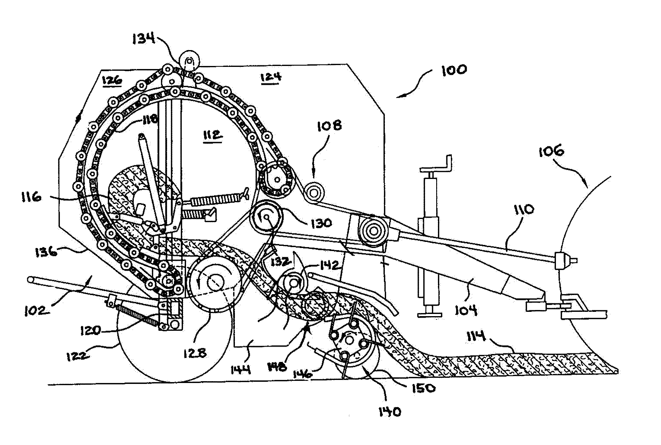
The above problems in the prior art have motivated the creation of a pickup and pickup mechanism having offset mounted pickup tines that reduce and / or substantially eliminate the dead area between the pickup tines and the rotor. The dead area being the space between the rotor tines and the rotor when the pickup is in the transfer position where the crop is not contacted or positively controlled by a member of feeder assembly of the machinery. The present invention is directed to embodiments of crop or forage pickup machinery having an improved pickup system comprising offset pickup tines. Embodiments of the present invention are particularly well suited, but in no way limited to, use with balers. The present invention may also find utility in use with round, square, or rectangular baler pickups and forage harvester pickups, for example.

Round balers are well known in the agricultural industry, and the instant invention can be used with substantially any of such machines. Reference is...


PUM

PropertyMeasurementUnit
longitudinal lengthaaaaaaaaaa
structureaaaaaaaaaa
shapeaaaaaaaaaa

Abstract

An improved pickup comprising offset pickup tines for improved feeding of balers or harverters. The offset mounting of the rotor tines and auger tines of the pickup reduces and / or substantially eliminates the “dead area” between the pickup and the rotor during the handing off of crop from one feed mechanism to another feeding mechanism resulting in improved control of the crop as the crop travels through the machine. The rotor tines and the auger tines may comprise the same structure providing improved efficiencies in manufacturing, inventory and maintenance of the pickup equipment.

Description

TECHNOLOGY FIELDThe present invention relates generally to pickups for crop and forage pick up and handling, and more particularly, to offset pickup tines for improved feeding of balers or harverters.BACKGROUNDFor many years agricultural balers have been used to consolidate and package crop material so as to facilitate the storage and handling of the crop material for later use. Usually, a mower-conditioner cuts and conditions the crop material for windrow drying in the sun. When the cut crop material is properly dried, a baler, most likely a round baler, is pulled along the windrows to pick up the crop material and form it into cylindrically-shaped round bales. More specifically, the pickups of the baler gather the cut and windrowed crop material from the ground then convey the cut crop material into a bale-forming chamber within the baler. The pickup assembly has a drive mechanism that operates to activate both the pickups, augers, and a rotor, and the pickup drive mechanism may b...

Claims


Application Information

Patent Timeline
Patent Type & Authority Applications(United States)
IPC IPC(8): A01D89/00A01D80/00B23P15/00
CPCA01D80/02Y10T29/49826Y10T29/49448A01D89/002
Inventor SMITH, KEVIN M.
Owner BLUE LEAF I P INC
Learn More