Exhaust gas turbocharger for an internal combustion engine of a motor vehicle

a technology of exhaust gas and internal combustion engine, which is applied in the direction of machines/engines, liquid fuel engines, transportation and packaging, etc., can solve the problems of reducing the load and speed range of internal combustion engines that cannot be attended to in an optimal manner, increasing the pressure at the exhaust gas outlet of the exhaust gas turbocharger, and comparatively low efficiency, so as to improve efficiency and widen the operating range , the effect of effective use of the expansion energy of individual cylinders

Active Publication Date: 2011-04-21
DAIMLER TRUCK AG
View PDF12 Cites 33 Cited by
  • Summary
  • Abstract
  • Description
  • Claims
  • Application Information

AI Technical Summary

Benefits of technology

[0017]In a further advantageous arrangement of the invention, the first and / or the second spiral channel comprises at least two spiral segment channels which are separated in a fluidic manner, and which can be coupled to different exhaust gas lines of the internal combustion engine. An exhaust gas turbocharger with a turbine formed with at least three flows is created in this manner, wherein the spiral segment channels enable an impact charging operating with a more effective use of the expansion energy of individual cylinders or cylinder groups. Lower load and speed regions of the internal combustion engine can hereby also be provided in an optimal manner, so that a considerable efficiency improvement is ensured over a wider operating range of the internal combustion engine. The flow cross-sectional area Aλ designates in this case the sum of the flow cross-sectional areas of the at least two spiral segment channels. The number of the spiral segment channels can thereby be adapted to the number of the cylinders or cylinder groups. It can also be provided that both spiral channels have two or more spiral segment channels. It can alternatively or additionally be provided that the turbine of the exhaust gas turbocharger comprises three or more spiral channels.
[0018]In order to be able to better adapt the operation of the turbine to the operation of the internal combustion engine, it has been shown to be advantageous in a further arrangement that the turbine comprises an inlet vane structure. A flow control depending on the geometric arrangement of the vane structure is facilitated hereby. The vane structure is adjustable whereby the inflow of the exhaust gas can advantageously be controlled depending on a load or flow rate. The vane structure can for example be mounted in the turbine housing so as to be translationally movable or the vanes are pivotally adjustable.
[0019]Particular advantages are obtained if the narrowest flow cross-sectional area Aλ of the first spiral channel and / or the narrowest flow cross-sectional area AAGR of the second spiral channel are formed by the vane structure and / or can be adjusted by the vane structure. A particularly high geometric variability of the turbine and a corresponding adjustability of the flow guidance is given in this manner. A further increase of the efficiency can be achieved hereby, as the corresponding spiral channel upstream of the vane structure can be provided with an enlarged cross-sectional area.

Problems solved by technology

These exhaust gas treatment systems lead to a pressure increase at an exhaust gas outlet of the exhaust gas turbocharger.
With the design limit conditions of exhaust gas turbochargers, which are usually defined by a nominal operating point, a charge change aspect and a fuel consumption aspect of the internal combustion engine, particularly the lower load and speed range of internal combustion engines can often not be attended to in an optimum manner even with exhaust gas turbochargers with two spiral inlet channels.
It is a disadvantage of the known exhaust gas turbochargers that they have comparatively low efficiencies, so that also the requirement of an internal combustion engine provided with the exhaust gas turbocharger relatively high.
This necessitates additional measures for an efficiency increase, whereby the manufacturing costs however also increase considerably.

Method used


Image

  • Exhaust gas turbocharger for an internal combustion engine of a motor vehicle
  • Exhaust gas turbocharger for an internal combustion engine of a motor vehicle
  • Exhaust gas turbocharger for an internal combustion engine of a motor vehicle

Examples


Embodiment Construction

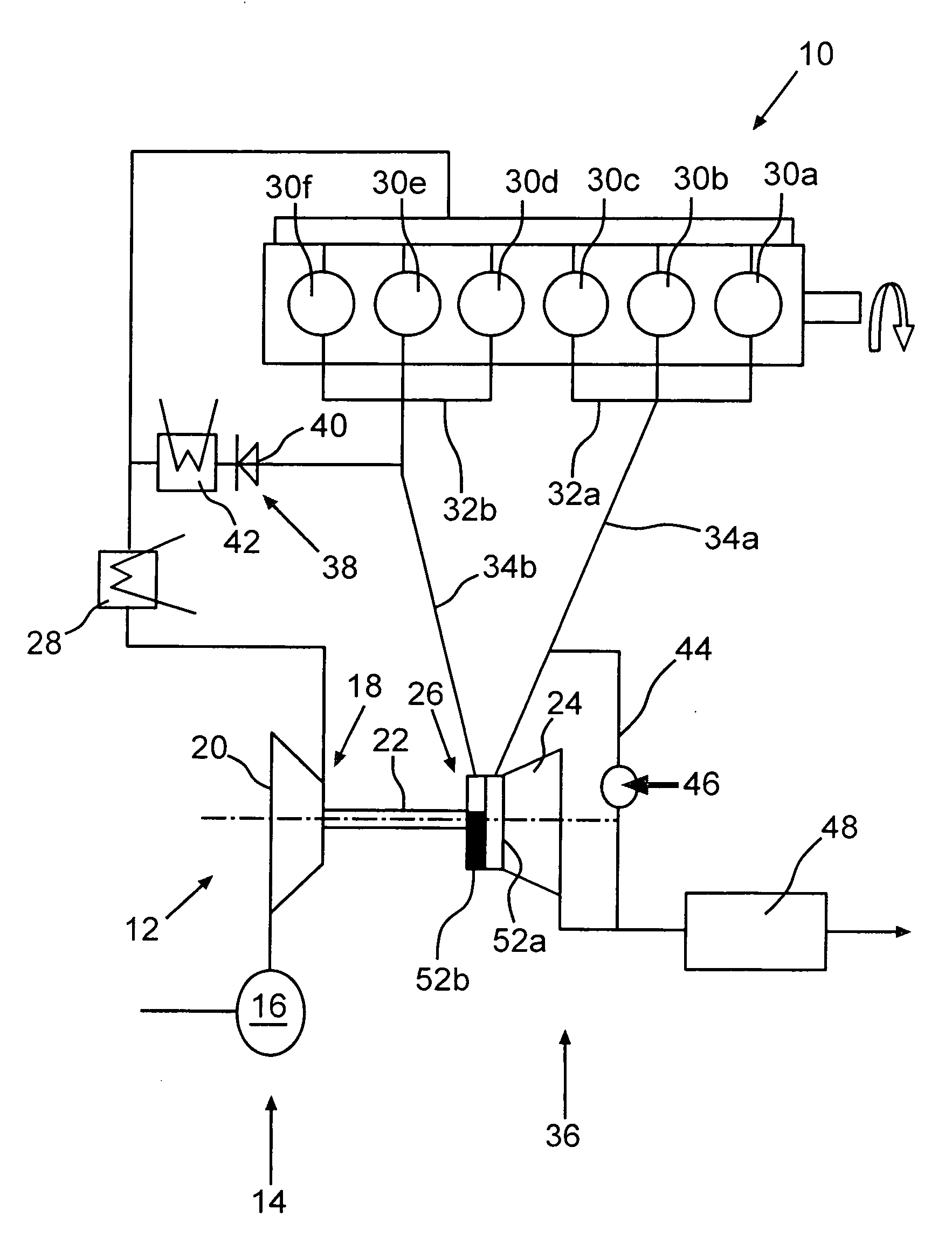
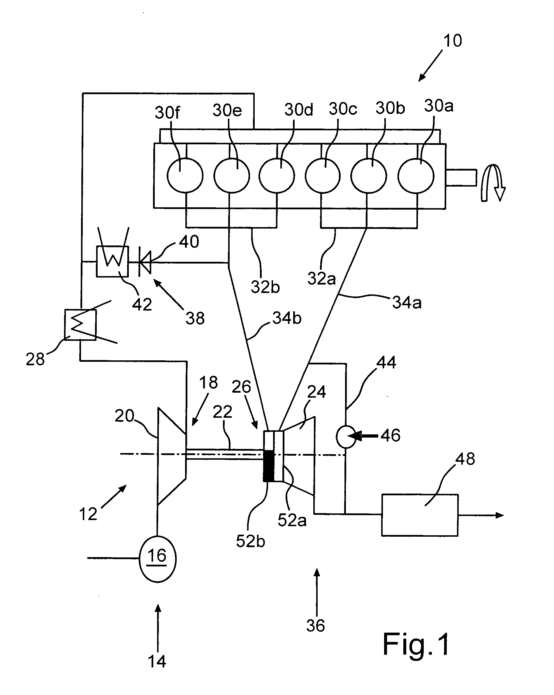
[0025]FIG. 1 shows schematically an internal combustion engine 10 of a motor vehicle (not shown), which is provided with an exhaust gas turbocharger 12. The internal combustion engine 10 comprises an intake tract 14 with an air filter 16. A compressor 18 of the exhaust gas 12 is arranged downstream of the air filter 16. The compressor 18 has a compressor wheel 20, which is connected rigidly to a turbine wheel 24 by means of a common shaft 22 of a turbine 26 of the exhaust gas turbocharger 12. The intake tract 14 includes a charge-air cooler 28 downstream of the compressor wheel 20. The internal combustion engine 10 is a Diesel engine in the present embodiment and comprises six cylinders 30a-f which are divided into two cylinder groups 32a, 32b, so that the individual cylinders 30a-f do not influence each other during a charge change. The cylinder groups are connected to the turbine 26 of the exhaust gas turbocharger via two separate exhaust gas lines 34a, 34b of an exhaust gas tract...


PUM


Abstract

In an exhaust gas turbocharger for an internal combustion engine of a motor vehicle with a turbine comprising a turbine housing with at least a first and a second spiral channel, each being coupled to an exhaust gas line of an exhaust gas tract of the internal combustion engine for conducting exhaust gas to a turbine wheel arranged within the turbine housing and driving a compressor wheel of a compressor of the exhaust gas turbocharger, an area ratio Qg of the turbine corresponds to the formula Qg=(Aλ+AAGR)/AR>0.40, wherein Aλ refers to a narrowest flow cross-section of the first spiral channel, AAGR to a narrowest flow cross-section of the second spiral channel (52b) and AR to a wheel exit flow cross-section of the turbine exhaust channel. The invention further relates to a motor vehicle with an internal combustion engine and such an exhaust gas turbocharger.

Description

[0001]This is a Continuation-In-Part Application of pending international patent application PCT / EP2009 / 005349 filed July 23, 2009 and claiming the priority of German patent application 10 2008 039 086.0 filed Aug. 21, 2008.BACKGROUND OF THE INVENTION[0002]The invention relates to an exhaust gas turbocharger for an internal combustion engine with a turbine housing having first and second spiral inlet channels for directing exhaust gas onto a turbine which is disposed in the turbine housing. The invention further relates to a motor vehicle with an internal combustion engine and such an exhaust gas turbocharger.[0003]Due to the continuous tightening of the emission limit values, for example the NOx and soot emission values of motor vehicles, the demands of exhaust gas turbochargers or charged internal combustion engines also increase. Thus, there are increasing demands regarding the charge pressure provision with high exhaust gas recirculation rates (AGR rate) over medium to high load...

Claims


Application Information

Patent Timeline
Patent Type & Authority Applications(United States)
IPC IPC(8): F02D23/00
CPCF01D17/141F01D17/18F02B29/0437F02B37/02F02B37/025F02B37/18F05D2220/40F02C6/12F02M25/0707F02M25/0731Y02T10/121Y02T10/144F02B37/24F02M26/05F02M26/28Y02T10/12
Inventor SUMSER, SIEGFRIEDKRATSCHMER, STEPHANMULLER, MARKUS
Owner DAIMLER TRUCK AG
Why Eureka
Try Eureka