
Portable multi-tube air sampler unit

a multi-tube, portable technology, applied in the field of air sampling devices, can solve the problems of limiting the mobility of users, the inability to place the entire unit back in service, and the user of the device, so as to prevent contaminant accumulation and carryover, and the effect of less tim

Inactive Publication Date: 2011-04-21
MIDWEST RES INST
View PDF39 Cites 26 Cited by
  • Summary
  • Abstract
  • Description
  • Claims
  • Application Information

AI Technical Summary

Benefits of technology

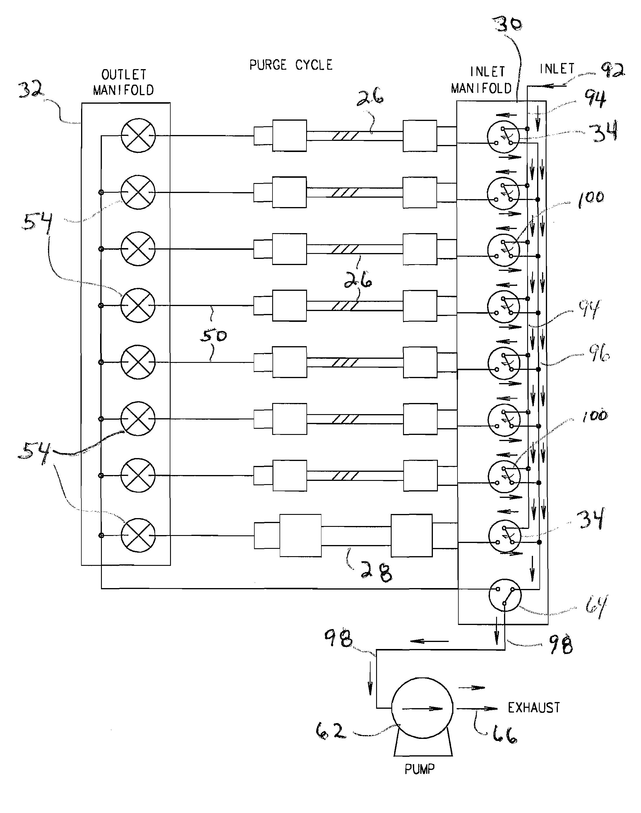
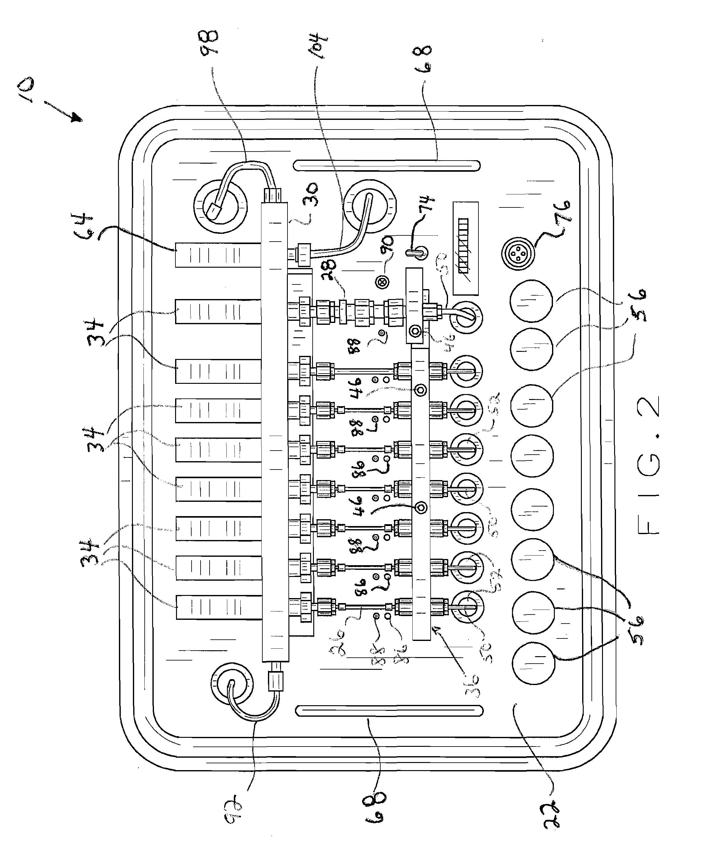
[0011]One end portion of each sampler tube is connected to a valve associated with the inlet manifold and the opposite end portion of each respective sampler tube is held in position within a hinged retainer bar mechanism which pivotally opens to allow for easy connection and removal of each respective tube. In addition, the opposite end portion of each respective tube sampler in the vicinity of the hinged retainer bar is attached to tubing which feeds through appropriate openings in a main system plate to the underside portion thereof for connection to the outlet manifold. The inlet and outlet manifolds each house a plurality of solenoid valves, one associated with the inlet portion and one associated with the outlet portion of each respective sample tube, for controlling both a purging operation and the sampling operation where air flow passes through a respective sample tube for collecting the trace element samples therewithin. A spare set of clean sample tubes are likewise housed within a storage compartment within the traveling case. The spare set of sample tubes increase the flexibility and usability of the present device in a contaminated area.
[0017]In addition, the present device may likewise include a heated inlet manifold and sample flow path so as to prevent contaminant accumulation and carryover; it may include a voice recorder operable from the controller unit or other location to allow audible collection of data and information such as recording location, sample identification, time and so forth; it may include a clean cycle option with a filter such as a charcoal filter valved into the inlet flow path and heating of the sample flow path to allow post-sampling purging to remove ambient contaminants after a sampling operation at a contaminated site; and it may include mechanisms to convert the present device to a desorbing auto sampler by adding an interface to instruments such as common gas chromatographs and mass spectrometers. This would include individual heated tubes, a heated exit transfer line, and a port to accept a controlled inert gas flow source. In this particular embodiment, the sampler tubes would not need to be operator replaceable and could be more tightly spaced.
[0018]In hazardous spill first responder situations and in potential chemical agent exposure situations, the present device will allow more samples to be taken in less time thereby allowing field personnel to spend less time in a potentially hazardous environment. The present device is also lighter and more easily carried by a first responder as compared to other known units. Once samples are taken, the first responder can return to a safe location where analysis can be conducted.

Problems solved by technology

Because of its construction, only one sample tube can be desorbed at a time; no additional sample tubes are provided in the overall unit; the individual sample tubes are not easily replaced; and the entire unit cannot be placed back in service until all of the individual tubes are desorbed and analyzed.
In the field, sampling / analysis turnaround time and battery power limit the user of this device to acquiring only 7 or 8 samples total per battery charge.
In addition, the HAPSITE unit's bulk and the necessity to analyze the samples on site limit the user's mobility and prolongs the exposure of field personnel to potentially hazardous environments.

Method used


Image

  • Portable multi-tube air sampler unit
  • Portable multi-tube air sampler unit
  • Portable multi-tube air sampler unit

Examples


Embodiment Construction

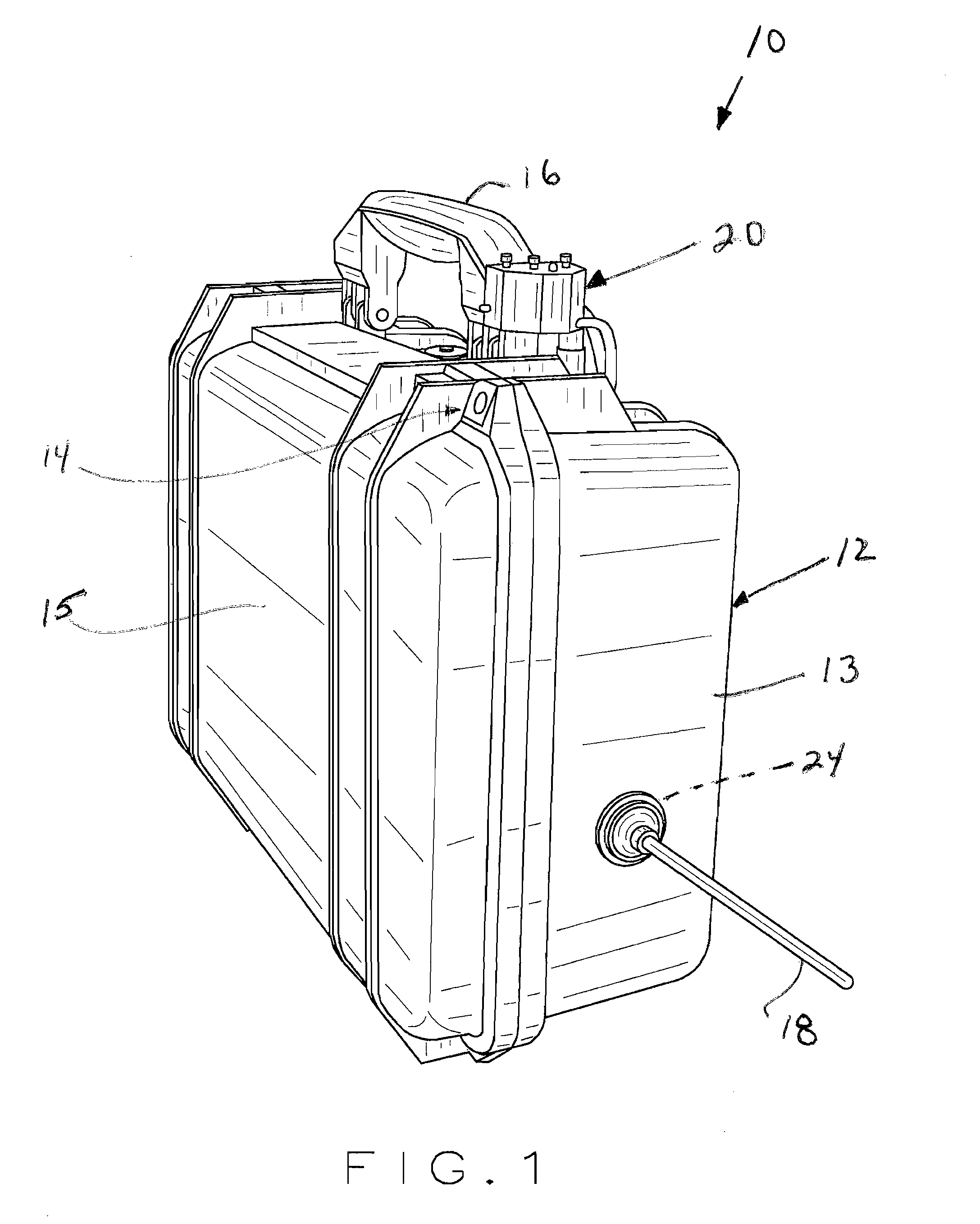
[0031]Referring to the drawings more particularly by reference numbers wherein like numerals refer to like parts, the number 10 in FIG. 1 identifies one embodiment of the present portable multi-tube air sampler device constructed according to the teachings of the present invention. The present multi-tube air sampler device 10 includes a lightweight portable carrying case or travel case 12 which houses all of the working components of the present device as will be hereinafter further explained. The carrying case 12 is preferably weather resistant and sufficiently rugged so as to withstand repeated field use including travel to and from a plurality of different types of contaminated environments. The case 12 opens and closes in a conventional manner similar to a typical briefcase or travel / luggage type case and includes a lower carrying case portion 13 and a top case portion 15. The carrying case portions 13 and 15 may be hingedly attached to each other in a conventional manner, or th...


PUM


Abstract

A portable multi-tube air sampler device for capturing samples of trace elements in a suspected contaminated environment which includes a plurality of sample tubes for collecting sample trace elements, parallel inlet and outlet manifolds which minimize the length of the sample inlet path while utilizing short straight sample tubes, a hinged retainer bar mechanism which allows for easy removal and replacement of the various sample tubes, and a removably attachable controller unit which can be installed on the exterior portion of the carrying case for controlling the operation of the sampling protocol. Other embodiments include heated inlet manifold and sample intake paths to prevent contamination accumulation and carryover, a clean cycle option with a filter valved into the inlet flow path to enhance the purging cycle, and a mechanism for converting the present device to a desorbing auto sampler configuration. The present system likewise incorporates a purging cycle prior to each sampling cycle.

Description

BACKGROUND OF INVENTION[0001]The present invention relates generally to air sampling devices used for gathering and analyzing trace elements from a particular environment such as a suspected contaminated area and, more particularly, to several embodiments of a lightweight, portable multi-tube sampler device capable of acquiring multiple samples of trace elements such as concentrations of chemical agents and toxic industrial chemicals for subsequent analysis by a mass spectrometer or other analyzing unit at a remote location.[0002]There are many applications in which it is desirable to collect and capture air samples from a particular environment suspected of contamination such as collecting air samples in potential hazardous chemical release situations, collecting vapor samples from bulk chemical storage locations, and / or collecting air samples in potential chemical agent release situations. Many different types of sampling devices exist today for capturing samples of trace elements...

Claims


Application Information

Patent Timeline
IPC IPC(8): G01N1/22G01N1/26
CPCG01N1/2273
Inventor LUDWICK, RICHARD K.WILSON, KEITH D.
Owner MIDWEST RES INST
Learn More