Systems and Methods for Powering a Variable Load with a MultiStage Flywheel Motor

a multi-stage flywheel motor and variable load technology, which is applied in mechanical energy handling, mechanical equipment, transportation and packaging, etc., can solve the problems of not being able to provide the peak power necessary to adequately propel a vehicle, single-stage flywheel motors are often unable to provide sustained power output when needed, and require a large amount of power for a variable duration. , to achieve the effect of increasing the moment of inertia

Inactive Publication Date: 2011-04-21
FIELDS ZANE C
View PDF0 Cites 9 Cited by
  • Summary
  • Abstract
  • Description
  • Claims
  • Application Information

AI Technical Summary

Benefits of technology

[0026]In accordance of a further aspect of the present invention, is a method of storing energy in a multi-rotor flywheel system that includes adding rotational energy to a primary rotor affixed to a driveshaft by applying a tangential force to the primary rotor, adding rotational energy to a secondary rotor rotatably coupled to the driveshaft by applying a tangential force to the secondary rotor; and activating a first thrust mechanism to frictionally engage the secondary rotor with the primary rotor, such that the primary and secondary rotors couple to increase the moment of inertia applied to the driveshaft.
[0027]In accordance with another aspect of the present invention, the method of storing energy in a multi-rotor flywheel system further includes adding rotational energy to a tertiary rotor that is rotatably coupled to the driveshaft by applying a tangential force to the tertiary rotor, and activating a second thrust mechanism to frictionally engage the tertiary rotor with the primary rotor such that the primary, secondary, and tertiary rotors couple to increase the moment of inertia affixed to the driveshaft.

Problems solved by technology

These vehicles generally require a large amount of power for a variable duration when accelerating quickly, climbing a hill, traversing rugged terrain, or the like.
In this regard, the flywheel acts as an energy reservoir capable of meeting the peak power demands of a vehicle whereas the small electric motor or other energy input mechanism, by itself, would not be capable of providing the peak power necessary to adequately propel a vehicle.
Unfortunately, these single-stage flywheel motors are often unable to provide sustained power output when needed, such as in situations where a vehicle is towing a trailer, carrying large load, traveling on and incline or at high rate of speed, etc.
In these taxing scenarios, existing flywheel motors often fail under sustained operation if the vehicle's demand for power is greater than the power being provided by the small electric motor or other energy input mechanism.
A principle method of increasing the moment of inertia is to increase the radius of the flywheel, which may be impractical given space constraints aboard vehicles.
Unfortunately, extremely high angular velocities create an increased risk of catastrophic rotor burst.
The problem associated with catastrophic rotor burst is compounded aboard vehicles, which are susceptible to collisions that could trigger a catastrophic rotor burst.
Aside from obvious safety concerns, technologies used to facilitate extremely high rotational velocities, such as vacuums, magnetic levitation, and advanced materials technology, may be cost-prohibitive for mass production and / or widespread usage.
Increasing the mass of a flywheel rotor often will increase the size and weight of the rotor and this may be impractical given large start-up torque requirements, as well as space, weight, installation, and maintenance considerations aboard vehicles.
Moreover, if a rotor with an increased mass were to experience a catastrophic rotor burst, the burst would be more destructive than a similar failure of a flywheel rotor having lesser mass.
However, switching to an energy input mechanism with greater power typically negatively impacts the economy and efficiency of the flywheel motor system, since it requires more power to operate.
Moreover, it may be impractical to have both a larger electric motor and a flywheel aboard a vehicle given space, weight and other considerations.

Method used


Image

  • Systems and Methods for Powering a Variable Load with a MultiStage Flywheel Motor
  • Systems and Methods for Powering a Variable Load with a MultiStage Flywheel Motor
  • Systems and Methods for Powering a Variable Load with a MultiStage Flywheel Motor

Examples


Embodiment Construction

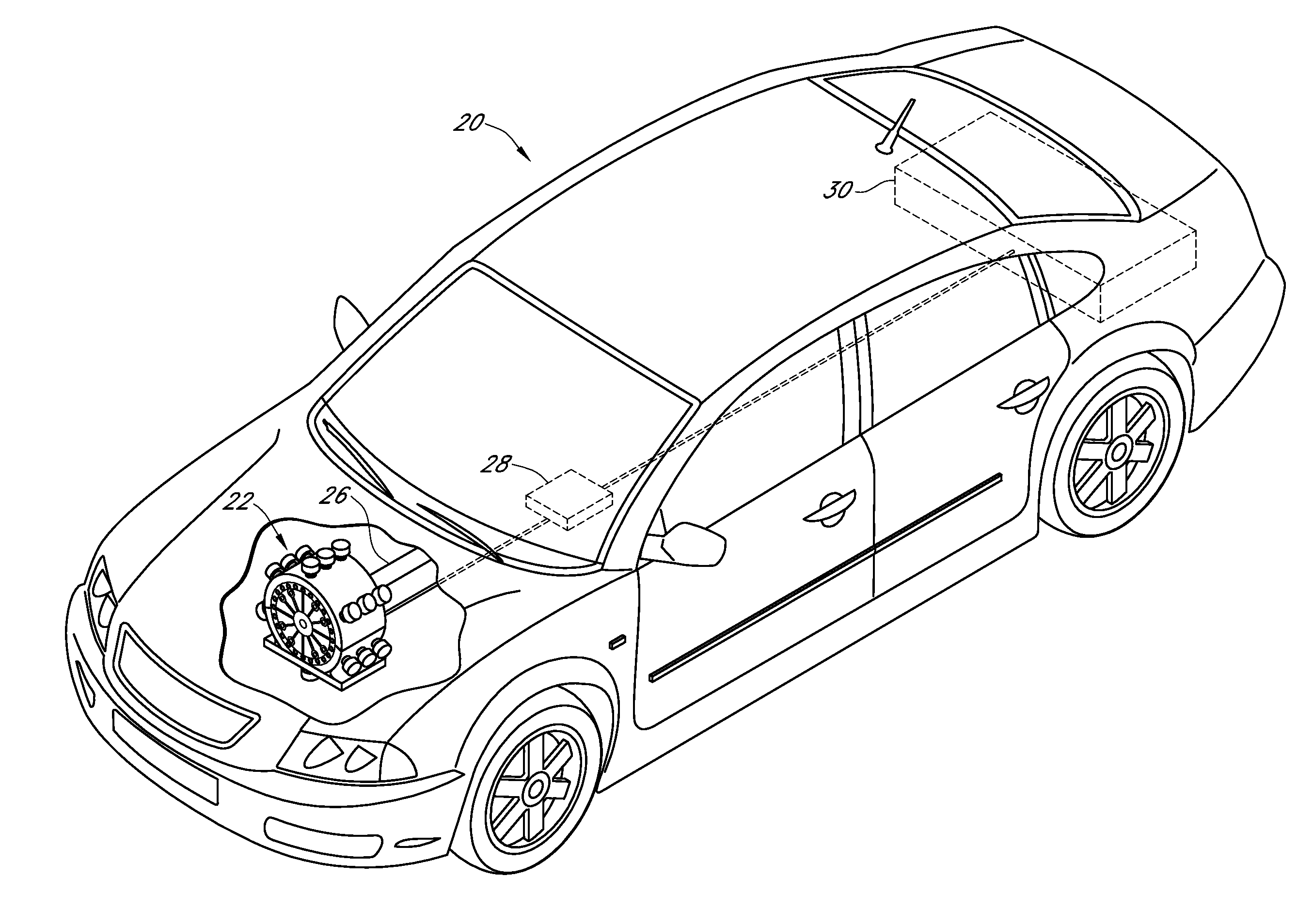
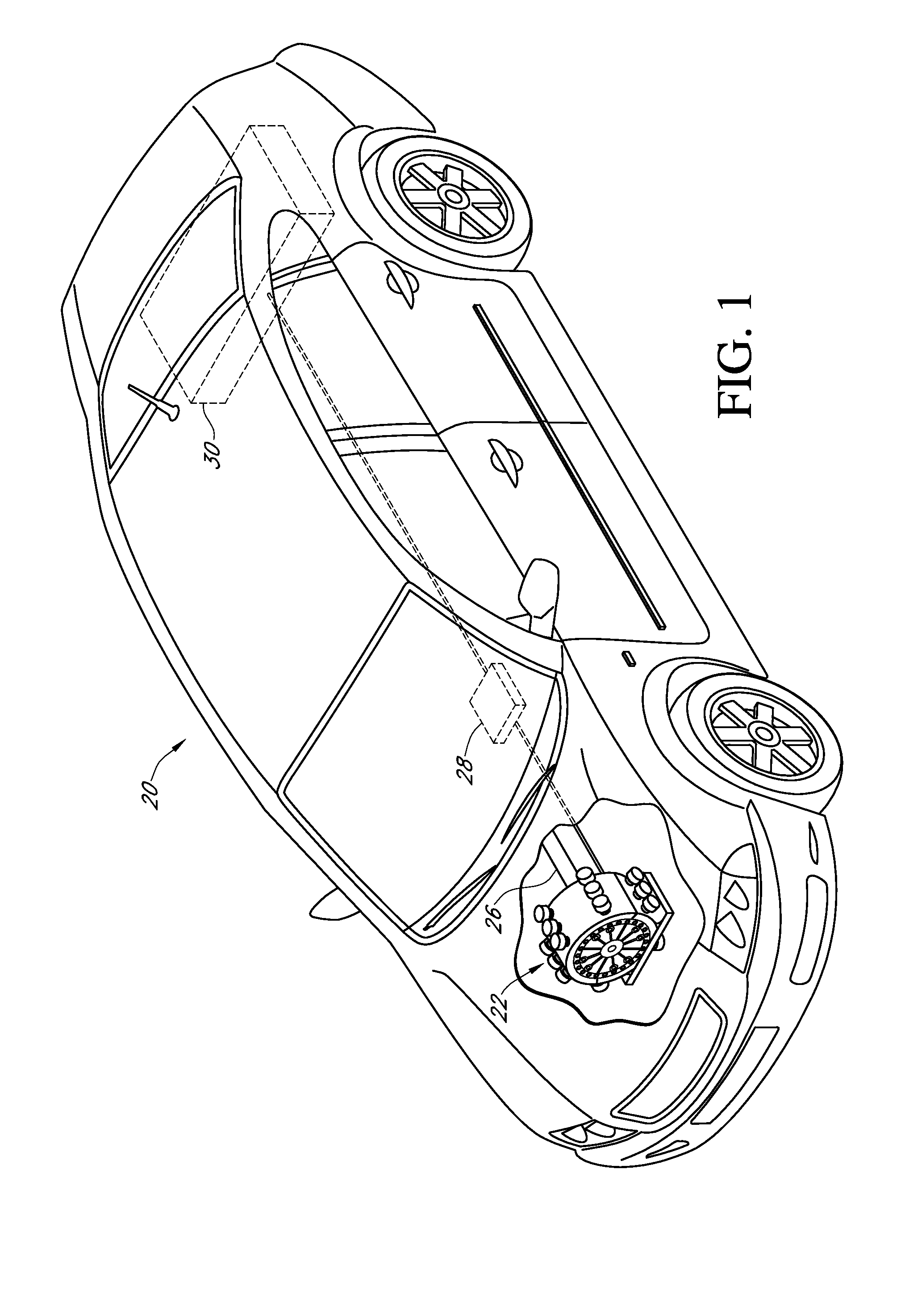
[0044]In accordance with an exemplary embodiment of the present invention, FIG. 1 depicts a multi-stage flywheel motor assembly 22 (also referred to herein as a “flywheel motor assembly” or a “flywheel motor”) mounted in the front engine compartment of an automotive vehicle 20. The flywheel motor assembly 22 may be mounted within the confines of a vehicle 20 in any manner well known in the Art (e.g., such as with vibration-isolating mounts), without departing from the spirit and scope of the present invention.

[0045]A power source 30 may be connected to the flywheel motor assembly 22 via a controller 28. The power source 30 is preferably a battery array, but may also be a super capacitor, fuel cell, generator, or the like. Alternatively, the power source 30 may provide non-electrical power such as a hydraulic or pneumatic power to drive the flywheel motor 22. In accordance with various embodiments, the controller 28 may manage, convert, distribute and / or condition energy emanating fr...


PUM


Abstract

A multi-rotor flywheel motor system for powering a vehicle. The flywheel motor system includes at least the following components: a plurality of flywheel rotors, a housing assembly, an energy input mechanism for each of the flywheel rotors, a plurality of pressure plates, and a crankshaft. The flywheel rotors are configured such that they may be frictionally coupled or decoupled and powered or non-powered in various combinations. In this regard, the flywheel motor system is able to efficiently meet the power demands of a vehicle in a range of operating conditions.

Description

CROSS REFERENCE TO RELATED APPLICATIONS[0001]This application is a continuation-in-part of U.S. patent application Ser. No. 12 / 168,105, filed Sep. 28, 2008, now pending, which is incorporated by reference in its entirety.FIELD OF THE INVENTION[0002]The field of the present invention generally relates to systems and methods associated with the utilization of a multi-stage flywheel motor. Specifically, the invention relates to a flywheel motor adapted with one or more auxiliary rotors that can be coupled with or decoupled from a primary flywheel rotor in order to optimally meet the changing power demands of a variable load, such as a load associated with a motor vehicle.BACKGROUND OF THE INVENTION[0003]In the field of zero-emission motor design, it is desirable to utilize flywheel energy storage devices that operate by accelerating a flywheel rotor to a desired angular velocity, thus increasing the kinetic energy of the flywheel rotor and the available energy stored within the flywhee...

Claims


Application Information

Patent Timeline
Patent Type & Authority Applications(United States)
IPC IPC(8): B60K6/10F16C15/00
CPCH02K7/025Y10T74/2117Y02E60/16H02K7/108
Inventor FIELDS, ZANE C.
Owner FIELDS ZANE C
Why Eureka
Try Eureka