Apparatus and method for adjusting parameter of impedance control

a technology of impedance control and apparatus, applied in the direction of programmed control, manipulators, instruments, etc., can solve the problems of unstable control system, inability to execute operation for a long time, and inability to absorb position errors

a technology of impedance control and apparatus, applied in the direction of programmed control, manipulators, instruments, etc., can solve the problems of unstable control system, inability to execute operation for a long time, and inability to absorb position errors

US20110093120A1Inactive Publication Date: 2011-04-21YASKAWA DENKI KK

Image

  • Apparatus and method for adjusting parameter of impedance control
  • Apparatus and method for adjusting parameter of impedance control
  • Apparatus and method for adjusting parameter of impedance control

Examples


Embodiment Construction

[0037]Embodiments will now be described with reference to the accompanying drawings, wherein like reference numerals designate corresponding or identical elements throughout the various drawings.

[0038]Embodiments of the present invention will be described below with reference to the drawings.

[0039]First, a system configuration of a general industrial robot and impedance control and, after that, techniques related to the present invention will be described.

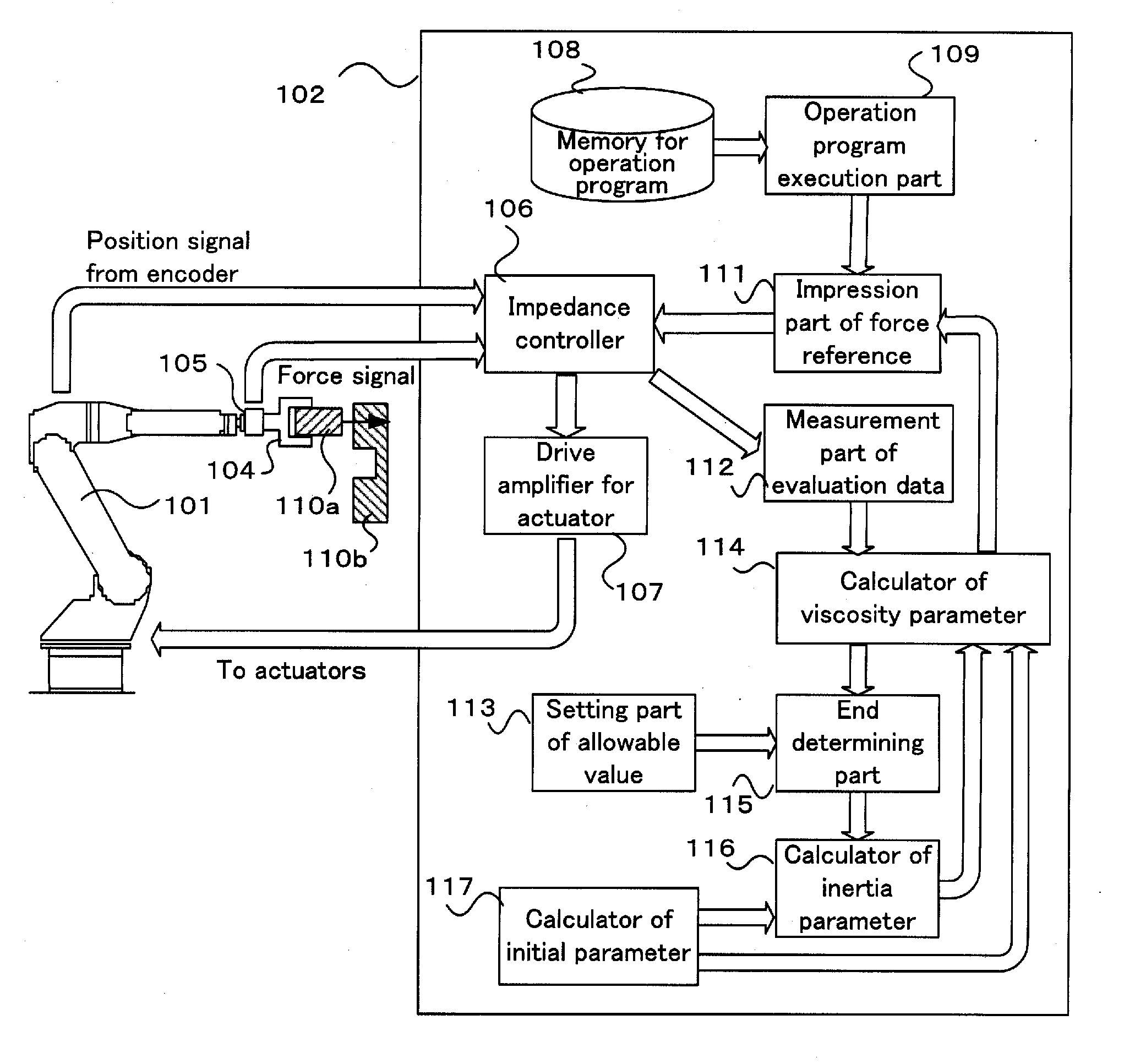
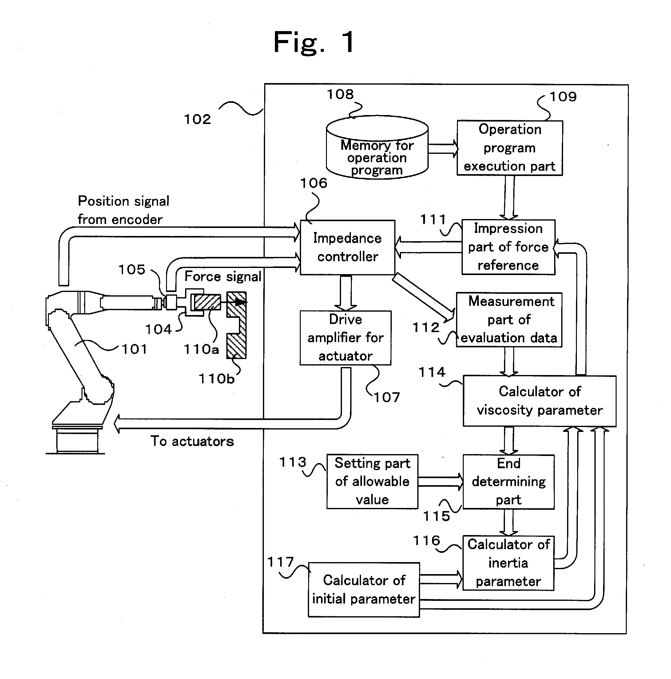
[0040]FIG. 7 is a configuration diagram of a general industrial robot. The configuration diagram shows a manipulator, a controller, and a portable teaching operation panel. In FIG. 7, a robot 101 is a manipulator having a plurality of joint axes and links. In each of the joint axes, a drive motor with an encoder is provided. The axes can be driven independently of each other. A controller 102 for the robot 101 is an apparatus for performing a feedback control (positional control system) based on an encoder signal of each of the joi...


PUM


Abstract

An apparatus has a parameter initial value calculator, a force reference impression part, an evaluation data measurement part, an allowable value setting part, a viscosity parameter calculator, an end determining part, and an inertia parameter adjusting part. The force reference impression part intermittently supplies a force reference to an impedance controller. The evaluation data measurement part measures setting time of time response, an overshoot amount, and the number of vibration times. The allowable value setting part sets allowable values of the overshoot amount and the setting time. The viscosity parameter calculator calculates a viscosity parameter with which the setting time becomes shortest. The end determining part determines the end or continuation of the process by comparing the adjustment values with the allowable values. The inertia parameter calculator adjusts the inertia parameter according to the adjustment values of the overshoot amount and the setting time.

Description

CROSS-REFERENCE TO RELATED APPLICATIONS[0001]The present application claims priority under 35 U.S.C. §119 to Japanese Patent Application No. 2009-241324 filed Oct. 20, 2009. The contents of the application are incorporated herein by reference in their entirety.BACKGROUND OF THE INVENTION[0002]1. Field of the Invention[0003]The present invention relates to an apparatus and method for adjusting parameters of impedance control based on information of a force sensor provided for an end effector of an industrial robot.[0004]The impedance control denotes a control on a position and a force for setting mechanical impedances (inertia, damping coefficient, and rigidity) which are generated in the case where a force is applied from the outside to the end of a robot to values convenient to a target work.[0005]2. Discussion of the Background[0006]There is a widely known technique that, in the case of executing a contact work such as mating by using an industrial robot, a force sensor is attache...

Claims


Application Information

Patent Timeline
21 Apr 2011
Publication
US20110093120A1
IPC
G05B15/00
CPC
B25J9/1638; B25J9/1633; G05B2219/39343; B25J9/1664; G05B2219/41387; G05B2219/39188; B25J9/1641; B25J13/085
Inventors
ANDO, SHINGO; NAGAI, RYOICHI