
Starter device for a motor driven machine

a technology of starting device and internal combustion engine, which is applied in the direction of engine starter, machine/engine, engine components, etc., can solve the problems of high force required for setting the starting device, elastically deformable tappet, and substantial load to be overcome by the user, so as to reduce the transmission ratio, shorten the effective length of the coupling rod, and increase the torque

Inactive Publication Date: 2011-04-28
DOLMAR
View PDF12 Cites 4 Cited by
  • Summary
  • Abstract
  • Description
  • Claims
  • Application Information

AI Technical Summary

Benefits of technology

[0013]It is therefore advantageous if a low transmission ratio is adjusted in the gear unit during the compression stroke of the internal combustion engine and a high transmission ratio is adjusted in the gear unit during the expansion stroke of the internal combustion engine. This needs to be correspondingly adapted to the design of the internal combustion engine in the form of a two-stroke engine or a four-stroke engine. In this case, it is preferred that the transmission ratio of two-stroke engines respectively changes in the same fashion during one revolution of the crankshaft while the change of the transmission ratio respectively takes place during two revolutions of the crankshaft in four-stroke engines.
[0031]An additional development of the inventive starter device may be realized with an electric motor for introducing the starter torque into the output element. An advantageous embodiment of the inventive design of the functional connection between the output element and the crankshaft is also achieved with the utilization of an electric motor because the electric motor can be realized smaller if the maximum torques in dependence on the crankshaft angle become smaller. Since a uniform torque demand results for an electric motor, an adaptation of the electric motor to the starter device is simplified.

Problems solved by technology

This represents a substantial load to be overcome by the user.
However, a very high force may also be required for setting the starter device in rotation at the beginning of the starting process depending on the piston position of the internal combustion engine.
Consequently, an elastically deformable tappet that is realized, for example, in the form of a coil spring cannot substantially smooth out the periodic pull rope force.
Even the slight difference in speed made possible by the elastically deformable tappet results in a slight deviation between the speed of the crankshaft and the speed of the rope spool.

Method used


Image

  • Starter device for a motor driven machine
  • Starter device for a motor driven machine
  • Starter device for a motor driven machine

Examples


Embodiment Construction

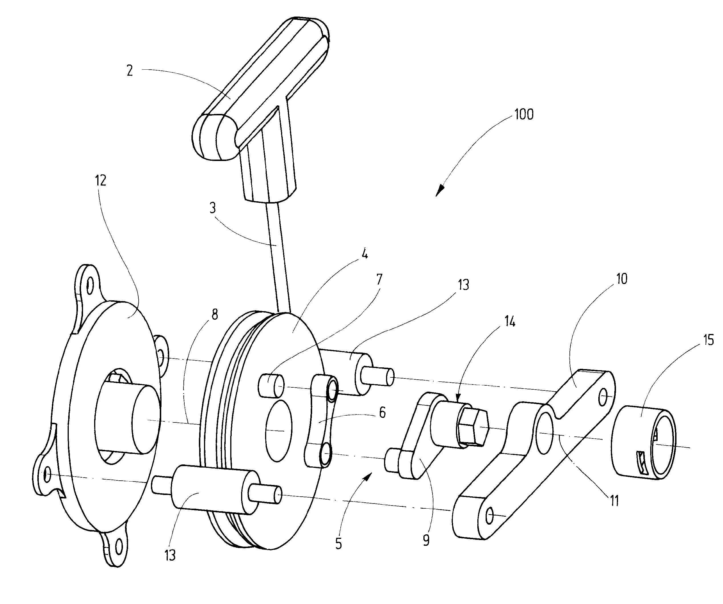
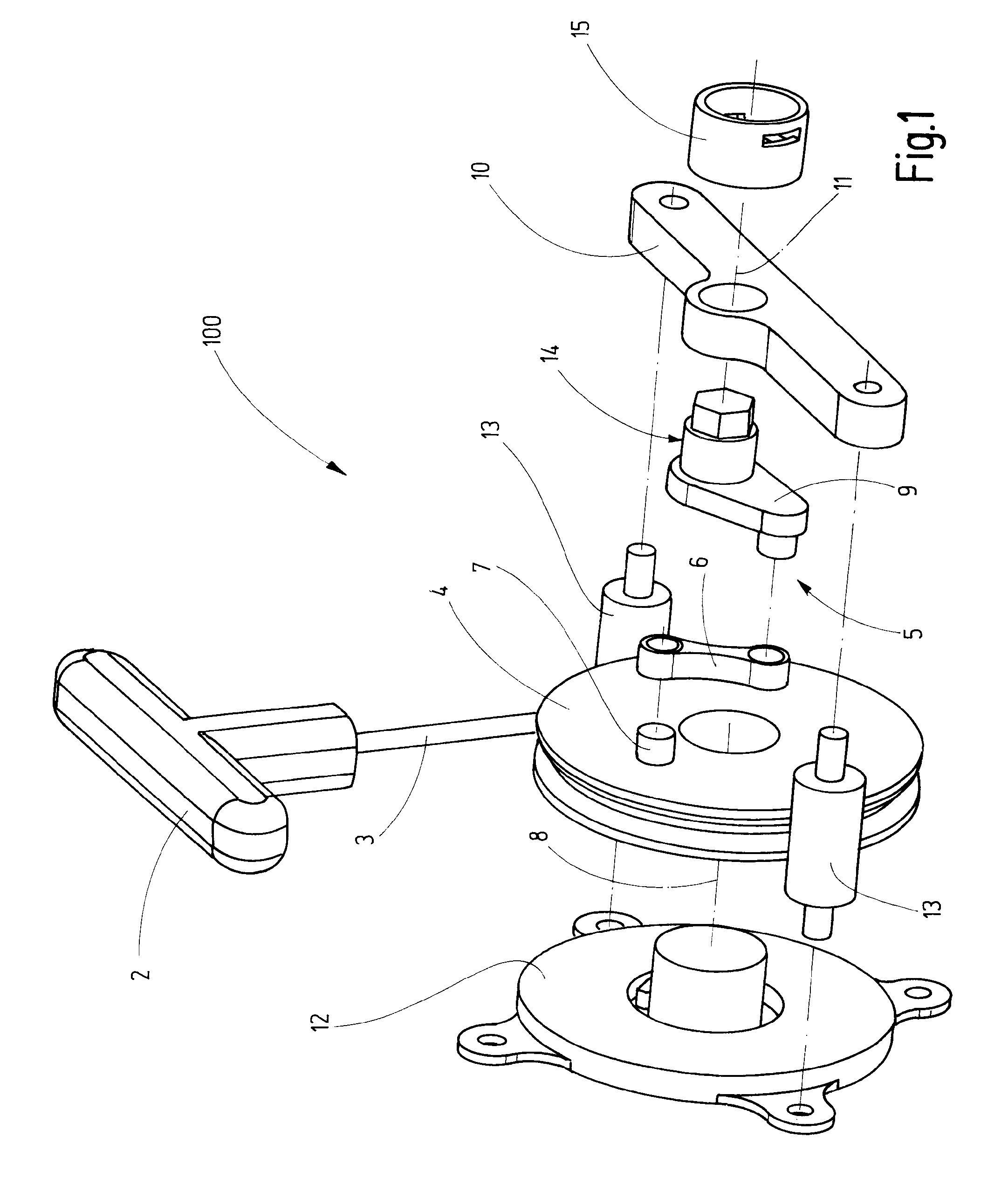
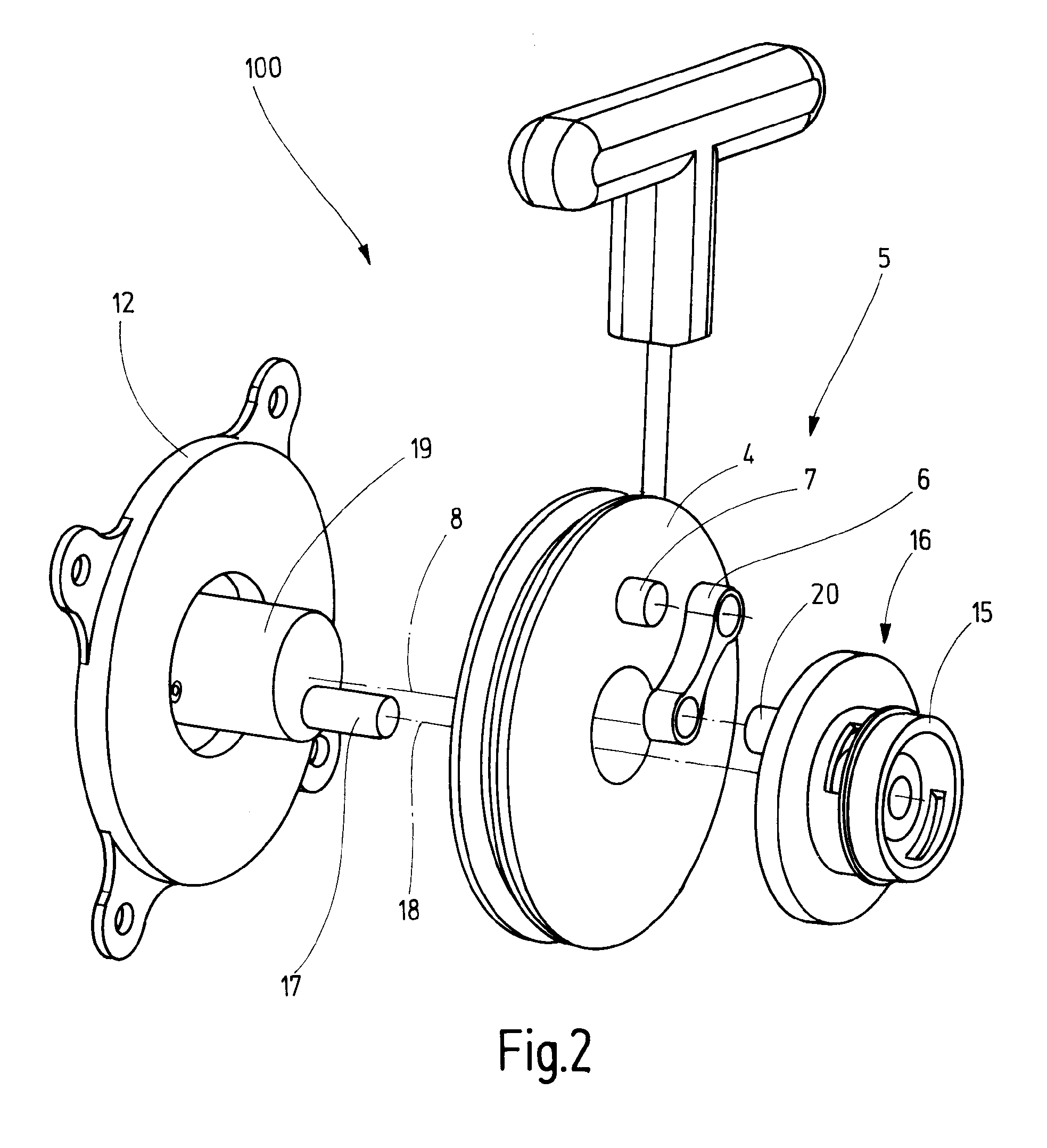
[0048]FIG. 1 shows a starter device that is identified by the reference symbol 100. The starter device 100 comprises a handle 2 that enables the user to introduce a pulling force into a starter pulling means 3. The starter pulling means 3 are realized in the form of a rope and wound up on a pulling means spool 4 in the form of a rope spool. If the user pulls on the starter pulling means 3, the pulling means spool 4 is set in rotation due to the unwinding of the starter pulling means 3 from the pulling means spool 4 such that a starter torque is introduced. The rotation of the pulling means spool 4 is transmitted to a coupling member 15, wherein the transmission is realized by means of a double crank mechanism 5.

[0049]The double crank mechanism 5 comprises a coupling rod 6 that is arranged between a hinge pin 7 situated on the plane side of the pulling means spool 4 and a lever arm 9. The rotational movement of the pulling means spool 4 causes the hinge pin 7 to rotate about a spool ...


PUM


Abstract

The invention pertains to a device for starting an internal combustion engine for handheld equipment such as chain saws, lawn mowers, lawn trimmers and the like, or for vehicles such as mopeds, boats or miniature aircraft. The starting device features an output element into which a starter torque can be introduced when the starting device is actuated. The output element is functionally connected to a crankshaft of the internal combustion engine in order to introduce a crankshaft torque therein. The functional connection between the output element and the crankshaft introduces variable crankshaft torque into the crankshaft depending on the rotational angle of the crankshaft at a constant starter torque. This advantageously improves force or torque characteristics for largely operating the starter device independently of the compression phase and the expansion phase of the internal combustion engine.

Description

FIELD OF THE INVENTION[0001]The present invention pertains to a starter device for starting an internal combustion engine as it is used, in particular, for handheld equipment, chain saws, lawn mowers, lawn trimmers and the like or an internal combustion engine for vehicles, particularly mopeds, boats or miniature aircraft. Such starter devices comprise an output element that may be realized in the form of a rotating shaft or a flange, into which a starter torque is introduced when the starter device is actuated, wherein the output element is functionally connected to the crankshaft of the internal combustion engine in order to introduce a crankshaft torque for starting the engine into the crankshaft. The starter device may be manually operated, wherein manually operated starter devices are usually provided with a pull rope, on the end of which a handle is arranged. Pulling on the pull rope causes a rope spool to be set in rotation, wherein the output element is only connected to the...

Claims


Application Information

Patent Timeline
Patent Type & Authority Applications(United States)
IPC IPC(8): F02N3/02
CPCF02N3/02Y10T74/13
Inventor KELLERMANN, CHRISTIAN
Owner DOLMAR
Learn More