
Fluorene derivative, light-emitting element, light-emitting device, electronic device, and lighting device

a technology of fluorene derivative and light-emitting element, which is applied in the direction of discharge tube luminescnet screen, diaryl/triaryl methane dye, other domestic articles, etc., can solve the problems of difficult to obtain light-emitting elements that emit light of good color, and increase the difficulty of lifetime, etc., to achieve high color purity, high reliability, and high emission efficiency

Active Publication Date: 2011-04-28
SEMICON ENERGY LAB CO LTD
View PDF31 Cites 36 Cited by
  • Summary
  • Abstract
  • Description
  • Claims
  • Application Information

AI Technical Summary

Benefits of technology

The present invention provides a novel fluorene derivative that can be used as a light-emitting material for organic EL elements. The fluorene derivative has a unique structure that includes a fluorene skeleton and an amine compound bonded through a sigma bond. The invention also provides a method for synthesizing the fluorene derivative. The technical effects of the invention include improved light-emitting efficiency, longer lifespan, and better stability of the light-emitting material. The fluorene derivative can be used in various electronic devices such as light-emitting devices, light-ing devices, and electronic devices.

Problems solved by technology

This is a feature that is difficult to obtain with point light sources typified by an incandescent lamp and an LED or linear light sources typified by a fluorescent lamp.
It is very difficult to obtain light-emitting elements that emit light of good color and to fulfill important conditions such as lifetime and power consumption.
Further, commercialization of light-emitting elements makes a lifetime increase an important issue.

Method used


Image

  • Fluorene derivative, light-emitting element, light-emitting device, electronic device, and lighting device
  • Fluorene derivative, light-emitting element, light-emitting device, electronic device, and lighting device
  • Fluorene derivative, light-emitting element, light-emitting device, electronic device, and lighting device

Examples


embodiment 1

[0116]In this embodiment, a fluorene derivative of one embodiment of the present invention is described.

[0117]A fluorene derivative of this embodiment is the fluorene derivative represented by General Formula (G1).

[0118]In General Formula (G1), R1 to R8 separately represent any of a hydrogen atom, an alkyl group having 1 to 6 carbon atoms, a substituted or unsubstituted phenyl group, or a substituted or unsubstituted biphenyl group. Further, α1 to α4 separately represent a substituted or unsubstituted phenylene group. Ar1 represents a substituted or unsubstituted condensed aromatic hydrocarbon having 14 to 18 carbon atoms forming a ring. Ar2 represents an aryl group having 6 to 13 carbon atoms forming a ring. Ar3 represents an alkyl group having 1 to 6 carbon atoms or a substituted or unsubstituted aryl group having 6 to 12 carbon atoms. Further, j, m, and n separately represent 0 or 1, and p represents 1 or 2.

[0119]An alkyl group is preferably used as a substituent in General Formu...

embodiment 2

[0155]In this embodiment, a fluorene derivative of one embodiment of the present invention is described.

[0156]A fluorene derivative of this embodiment is the fluorene derivative represented by General Formula (G3).

[0157]In General Formula (G3), R1 to R8 and R31 to R34 separately represent any of a hydrogen atom, an alkyl group having 1 to 6 carbon atoms, a substituted or unsubstituted phenyl group, or a substituted or unsubstituted biphenyl group. Further, α1 to α3 separately represent a substituted or unsubstituted phenylene group. Ar1 represents a substituted or unsubstituted condensed aromatic hydrocarbon having 14 to 18 carbon atoms forming a ring. Are represents a substituted or unsubstituted aryl group having 6 to 13 carbon atoms forming a ring. Ar3 represents an alkyl group having 1 to 6 carbon atoms or a substituted or unsubstituted aryl group having 6 to 12 carbon atoms. Further, j, m, and n separately represent 0 or 1, and p represents 1 or 2.

[0158]A fluorene derivative of...

embodiment 3

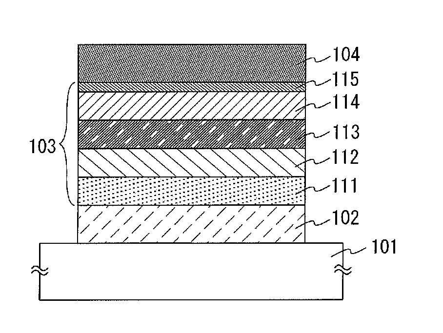
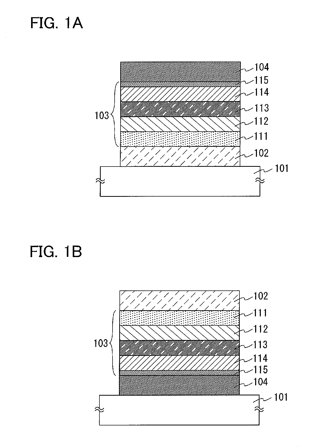
[0168]In this embodiment, a light-emitting element formed using the fluorene derivative according to Embodiment 1 or Embodiment 2 is described.

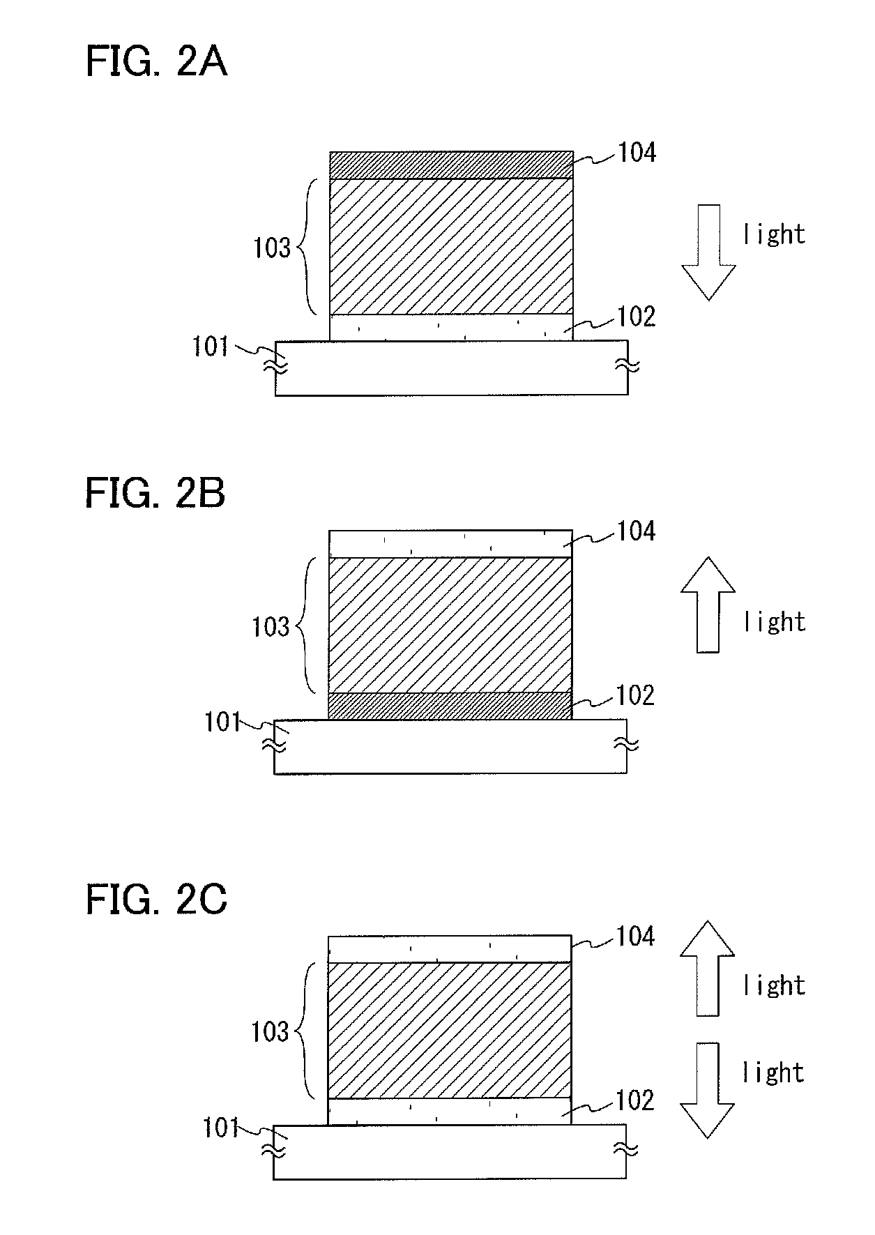
[0169]The light-emitting element in this embodiment includes a first electrode which functions as an anode, a second electrode which functions as a cathode, and an EL layer interposed between the first electrode and the second electrode. Note that the light-emitting element in this embodiment can exhibit light emission when a voltage is applied to each electrode so that the potential of the first electrode is higher than that of the second electrode.

[0170]In addition, the EL layer of the light-emitting element in this embodiment includes a first layer (hole-injection layer), a second layer (hole-transport layer), a third layer (light-emitting layer), a fourth layer (electron-transport layer), and a fifth layer (electron-injection layer), from the first electrode side.

[0171]A structure of the light-emitting element in this embodiment will be d...


PUM

PropertyMeasurementUnit
temperatureaaaaaaaaaa
work functionaaaaaaaaaa

Abstract

An object is to provide a new fluorene derivative as a good light-emitting material for organic EL elements. A fluorene derivative represented by General Formula (G1) is provided.In the formula, R1 to R8 separately represent a hydrogen atom, an alkyl group having 1 to 6 carbon atoms, a substituted or unsubstituted phenyl group, or a substituted or unsubstituted biphenyl group. Further, α1 to α4 separately represent a substituted or unsubstituted phenylene group. Ar1 represents a substituted or unsubstituted condensed aromatic hydrocarbon having 14 to 18 carbon atoms forming a ring. Ar2 represents a substituted or unsubstituted aryl group having 6 to 13 carbon atoms forming a ring. Ar3 represents an alkyl group having 1 to 6 carbon atoms or a substituted or unsubstituted aryl group having 6 to 12 carbon atoms. Further, j, m, and n separately represent 0 or 1, and p represents 1 or 2.

Description

BACKGROUND OF THE INVENTION[0001]1. Field of the Invention[0002]The present invention relates to a novel material applicable to a light-emitting element at least part of which includes an organic compound, and also relates to a light-emitting element, a light-emitting device, an electronic device, and a lighting device using the material.[0003]2. Description of the Related Art[0004]In recent years, research and development have been extensively conducted on light-emitting elements using electroluminescence (EL). In a basic structure of such a light-emitting element, a layer which includes a light-emitting substance is interposed between a pair of electrodes. By voltage application to this element, light emission can be obtained from the light-emitting substance having a light-emitting property.[0005]Since such a light-emitting element is of self-light-emitting type, it is thought that the light-emitting element has advantages over a liquid crystal display in that visibility of pixel...

Claims


Application Information

Patent Timeline
Patent Type & Authority Applications(United States)
IPC IPC(8): H01J1/62C07C211/54H10K99/00
CPCC07C211/61C09K11/06H01L51/0054H01L51/0058C09K2211/1014H01L51/5012H05B33/10C09K2211/1007C09K2211/1011H01L51/006C07C2601/14C07C2603/18C07C2603/24C07C2603/50H10K85/622H10K85/626H10K85/633H10K50/11Y10S428/917H10K50/00H05B33/14C07D307/78C07D471/04H10K2101/40H10K2101/30C07C211/54
Inventor OGITA, KAORISUZUKI, TSUNENORIOSAKA, HARUESEO, SATOSHI
Owner SEMICON ENERGY LAB CO LTD
Learn More