

Switching power supply unit
- Summary
- Abstract
- Description
- Claims
- Application Information
AI Technical Summary
Benefits of technology
Problems solved by technology
Method used
Image

Examples
second embodiment
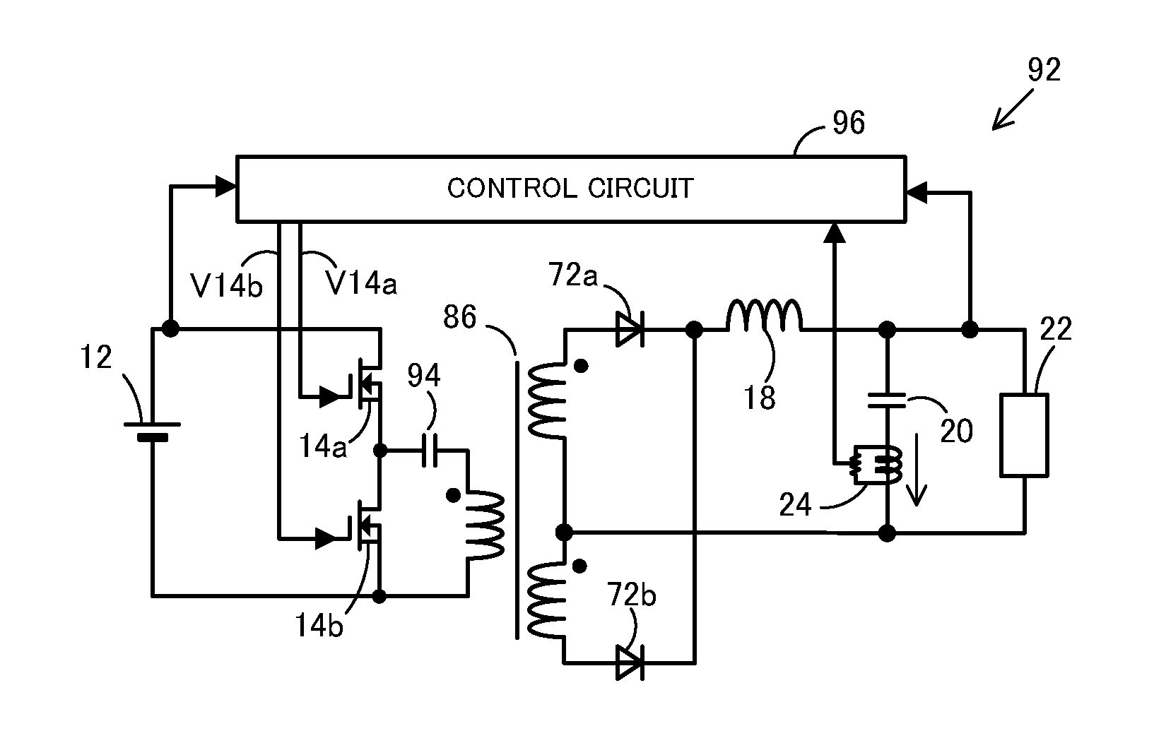
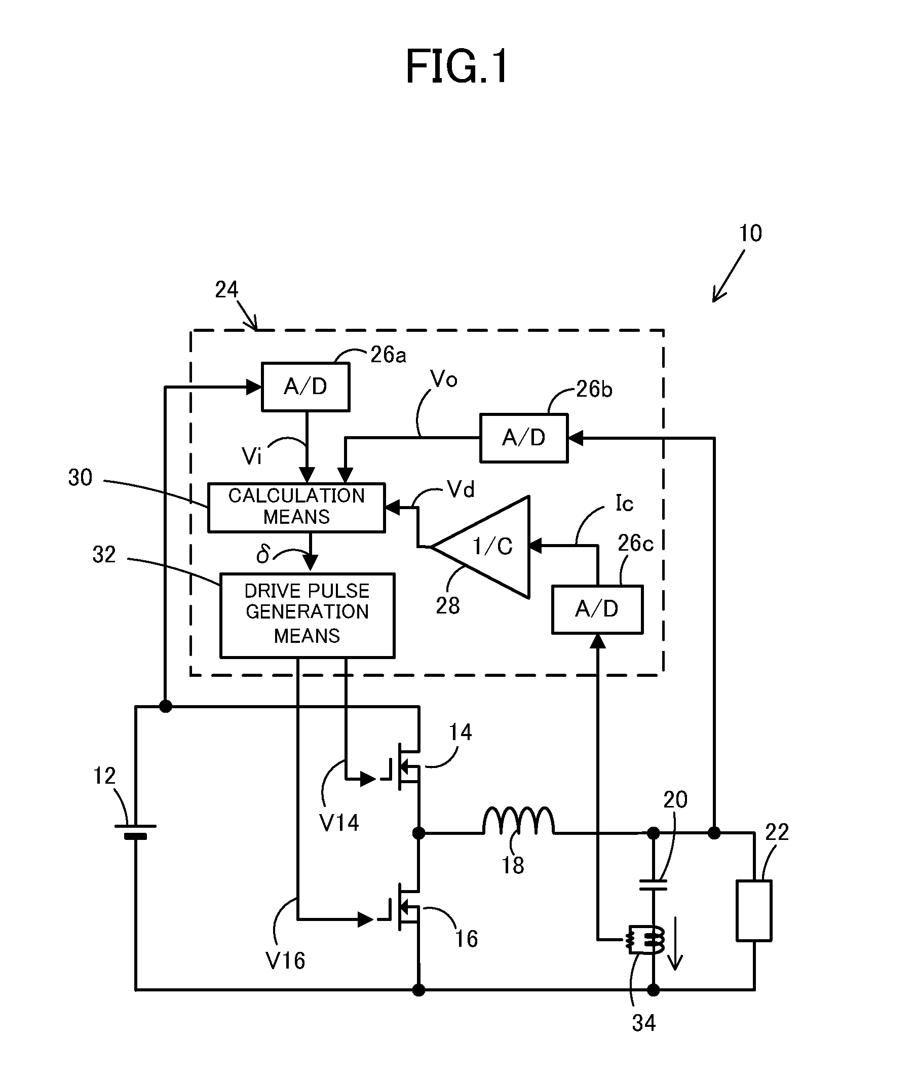
[0089]Next, a switching power supply unit 40 according to the present invention will be described with reference to FIGS. 6 and 7. Components similar to those of the above-described switching power supply unit 10 will be denoted by similar reference numerals and description thereof will be omitted. The switching power supply unit 40 has a configuration substantially similar to that of the switching power supply unit 10 illustrated in FIG. 1 except that the switching power supply unit 40 includes A / D converters 42a, 42b and 42c, a calculation means 44 and a drive pulse generation means 46 instead of the A / D converters 26a, 26b and 26c, the calculation means 30 and the drive pulse generation means 32. The A / D converters 42a, 42b and 42c, the calculation means 44 and the drive pulse generation means 46 behave differently from the A / D converters 26a, 26b and 26c, the calculation means 30 and the drive pulse generation means 32, respectively.
[0090]Analog information from each component i...
first embodiment
[0093]With the calculation means 44 and the drive pulse generation means 46, when the output differential value Vd (or the capacitor current signal Ic) is sampled in a duration in which no current is flowing through the smoothing inductor 18 (i.e., a zero current duration), control of the output using the output differential value Vd becomes impossible. However, as in the switching power supply unit 10 since the main switching element 14 and the rectifier 16 of the switching power supply unit 40 are bidirectionally conductive N-channel MOSFETs, even if, for example, the output current supplied to the load 22 is reduced to a critical point or below a critical point at which the current stops flowing in the circuit, the smoothing inductor 18 causes the current to continuously flow and thus the zero current duration does not appear. Accordingly, sampling can be performed at arbitrary time instants in the cycle of switching T.
[0094]Hereinafter, an operation of the switching power suppl...
third embodiment
[0095]Next, a switching power supply unit 50 according to the present invention will be described with reference to FIGS. 8 to 10. Components similar to those of the above-described switching power supply unit 10 will be denoted by similar reference numerals and description thereof will be omitted. The switching power supply unit 50 has a configuration substantially similar to that of the switching power supply unit 10 illustrated in FIG. 1 except that the switching power supply unit 50 includes A / D converters 52a, 52b and 52c, a calculation means 54 and a drive pulse generation means 56 instead of the A / D converters 26a, 26b and 26c, the calculation means 30 and the drive pulse generation means 32. The A / D converters 52a, 52b and 52c, the calculation means 54 and the drive pulse generation means 56 behave differently from the A / D converters 26a, 26b and 26c, the calculation means 30 and the drive pulse generation means 32, respectively.
[0096]Analog information from each component i...
PUM
 Abstract
Description
Claims
Application Information