Integrated circuit device and electronic apparatus
a circuit device and integrated circuit technology, applied in the direction of liquid/fluent solid measurement, instruments, sustainable buildings, etc., can solve the problems of inability to realize further reduction in the power consumption of short-range radio communication terminals, inability to eliminate contradictions, and unnecessary operation, so as to reduce the power consumption of electronic devices, eliminate contradictions, and achieve low power consumption.
- Summary
- Abstract
- Description
- Claims
- Application Information
AI Technical Summary
Benefits of technology
Problems solved by technology
Method used
Image
Examples
first embodiment
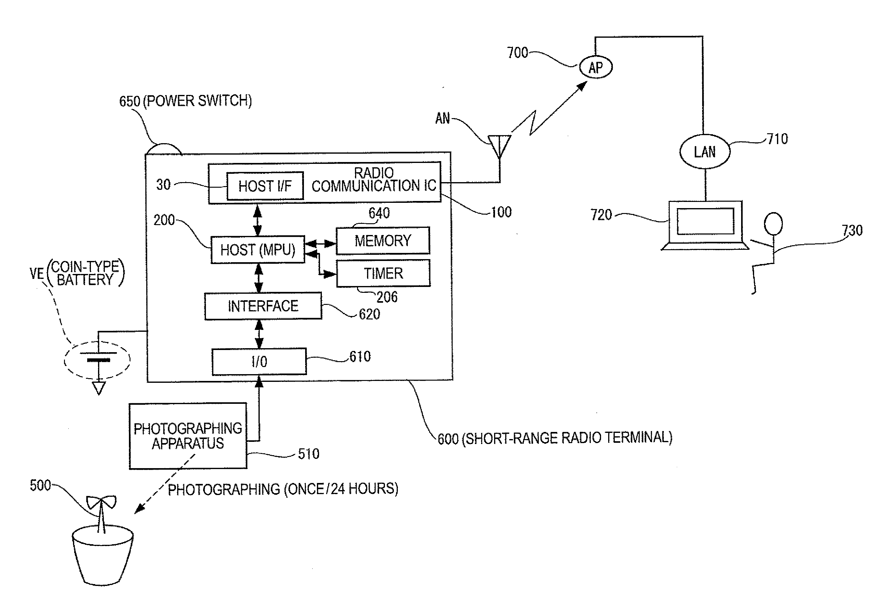
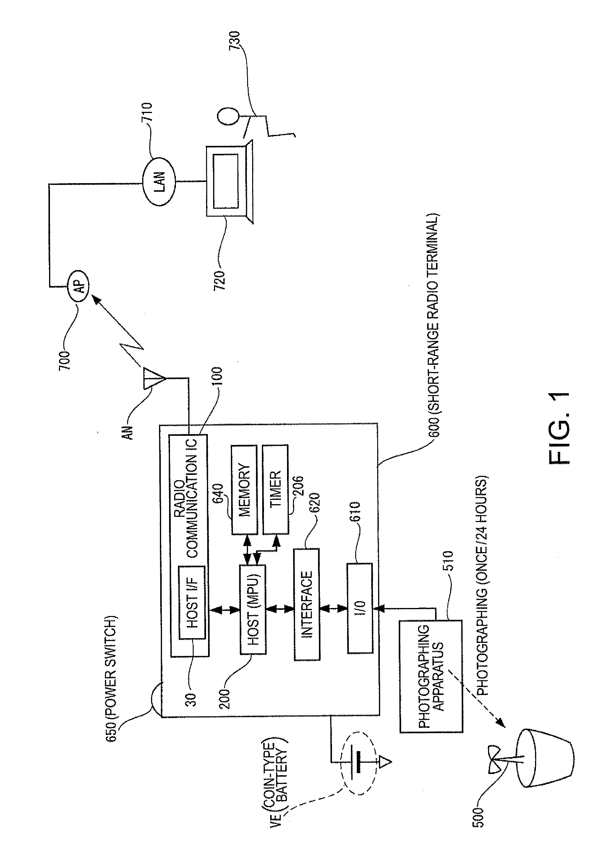
[0084]FIG. 1 is a diagram showing an example of a form of use of a short-range radio communication terminal. A radio communication system is adopted in a short-range radio communication terminal 600. The short-range radio communication terminal 600 includes an input and output unit (I / O) 610, an I / O interface 620, a host processor (e.g., MPU, hereinafter simply referred to as host) 200, a memory 640 (in which, for example, application software is stored), a timer 206, a radio communication IC (an integrated circuit device for radio communication) 100 (including a host interface (host I / F) 30), an antenna AN for radio communication, and a power switch 650. The short-range radio communication terminal 600 is a small, light, and ultra-low-power consumption radio portable terminal driven by, for example, a coin-type battery VE.
[0085]In the example shown in FIG. 1, the short-range radio communication terminal 600 is used for transmission of data indicating a growing state of a plant (or ...
second embodiment
[0123]In a second embodiment, examples of an internal configuration and operations of the radio communication IC 100 are specifically explained with reference to FIGS. 7 to 12. FIG. 7 is a diagram showing an example of a specific internal configuration of the radio communication IC. In FIG. 7, components same as those shown in the figures referred to above are denoted by the same reference numerals and signs. Redundant explanation of the components explained above is omitted. Only components added anew are explained.
[0124]As shown in a lower side of FIG. 7, the physical layer circuit (PHY) 15 includes the analog circuit unit 17 and a physical layer baseband control unit PHYBB. The analog circuit unit 17 includes a reception circuit RX, a transmission circuit TX, and a PLL circuit 12. In order to control the operation of the physical layer circuit (PHY) 15, a power control unit 20 and an active-mode-timing control unit 22 are provided. In order to prevent malfunction of a flip-flop d...
third embodiment
[0143]In a third embodiment, other examples of the internal configuration and the operations of the radio communication IC 100 are specifically explained with reference to FIGS. 13 to 16. FIG. 13 is a diagram showing another example of the specific internal configuration of the radio communication IC. In FIG. 13, components same as those shown in the figures referred to above are denoted by the same reference numerals and signs. Redundant explanation of the components explained above is omitted.
[0144]The host 200 includes a MPU 202, a memory 204 having application software stored therein, the timer 206 for time measurement, a clock generating circuit 208, and an I / O interface 210.
[0145]The data-link layer circuit and PHY control circuit 19 includes the host interface (host I / F) 30, a buffer 32, a higher-order-protocol processing unit (U) 34 (including a command processing unit), a lower-order-protocol processing unit (L) 36, a low-power-mode-timing control unit (U) 38, a low-power-m...
PUM
 Abstract
Description
Claims
Application Information
 - R&D
- Intellectual Property
- Life Sciences
- Materials
- Tech Scout
- Unparalleled Data Quality
- Higher Quality Content
- 60% Fewer Hallucinations
Browse by: Latest US Patents, China's latest patents, Technical Efficacy Thesaurus, Application Domain, Technology Topic, Popular Technical Reports.
© 2025 PatSnap. All rights reserved.Legal|Privacy policy|Modern Slavery Act Transparency Statement|Sitemap|About US| Contact US: help@patsnap.com


