Method and arrangement for exhaust-gas recirculation in an internal combustion engine

a technology of exhaust gas recirculation and internal combustion engine, which is applied in the direction of machines/engines, electrical control, mechanical equipment, etc., can solve the problems of relatively high particulate emissions in the case of diesel engines, droplets and particles can damage the compressor blades, and achieve the effect of reducing nox emissions and preventing excessive condensate quantities

Active Publication Date: 2011-05-05
FORD GLOBAL TECH LLC
View PDF8 Cites 17 Cited by
  • Summary
  • Abstract
  • Description
  • Claims
  • Application Information

AI Technical Summary

Benefits of technology

[0015]In some embodiments, the injection quantity is controlled as a function of the dew point of the air / exhaust-gas mixture supplied to the engine. It is possible in this way in particular to prevent excessive condensate quantities from being present in the air which is supplied to the engine.
[0016]According to an embodiment of the disclosure, the injection of the liquid condensate is regulated as a function of the exhaust-gas composition, in particular as a function of the nitrogen oxide content (NOx). For this purpose, it is possible for a sensor to be provided for measuring the present nitrogen oxide content in the exhaust gas, and also a controller for regulating the condensate injection. In this way, it is possible in a simple manner to obtain a particularly effective reduction of the NOx emissions.

Problems solved by technology

Such high-pressure EGR however has some disadvantages, for example relatively high particulate emissions in the case of diesel engines.
Nevertheless, even in this case, the condensate also contains residual particles and particulate matter from the exhaust system which may for example have become detached, as a result of wear or as a result of chemical or mechanical influences, from the particulate filter or from other components of the EGR system.
If the condensate, which is entrained in droplet or particle form, in the exhaust gas now passes into the compressor as a result of being added to the charge air taking place upstream of the compressor, the droplets and the particles can damage the compressor blades on account of the very high speeds of the compressor blades.
This process and apparatus are associated with a comparatively high level of technical expenditure.
In the event of insufficient heating, it is not possible to prevent the discharge of harmful acids to the environment.
Furthermore, in embodiments with filters in the condensate line, the particulate matter is removed, and thus not supplied into the engine.

Method used


Image

  • Method and arrangement for exhaust-gas recirculation in an internal combustion engine
  • Method and arrangement for exhaust-gas recirculation in an internal combustion engine

Examples


Embodiment Construction

[0021]As those of ordinary skill in the art will understand, various features of the embodiments illustrated and described with reference to any one of the FIGURES may be combined with features illustrated in one or more other FIGURES to produce alternative embodiments that are not explicitly illustrated or described. The combinations of features illustrated provide representative embodiments for typical applications. However, various combinations and modifications of the features consistent with the teachings of the present disclosure may be desired for particular applications or implementations.

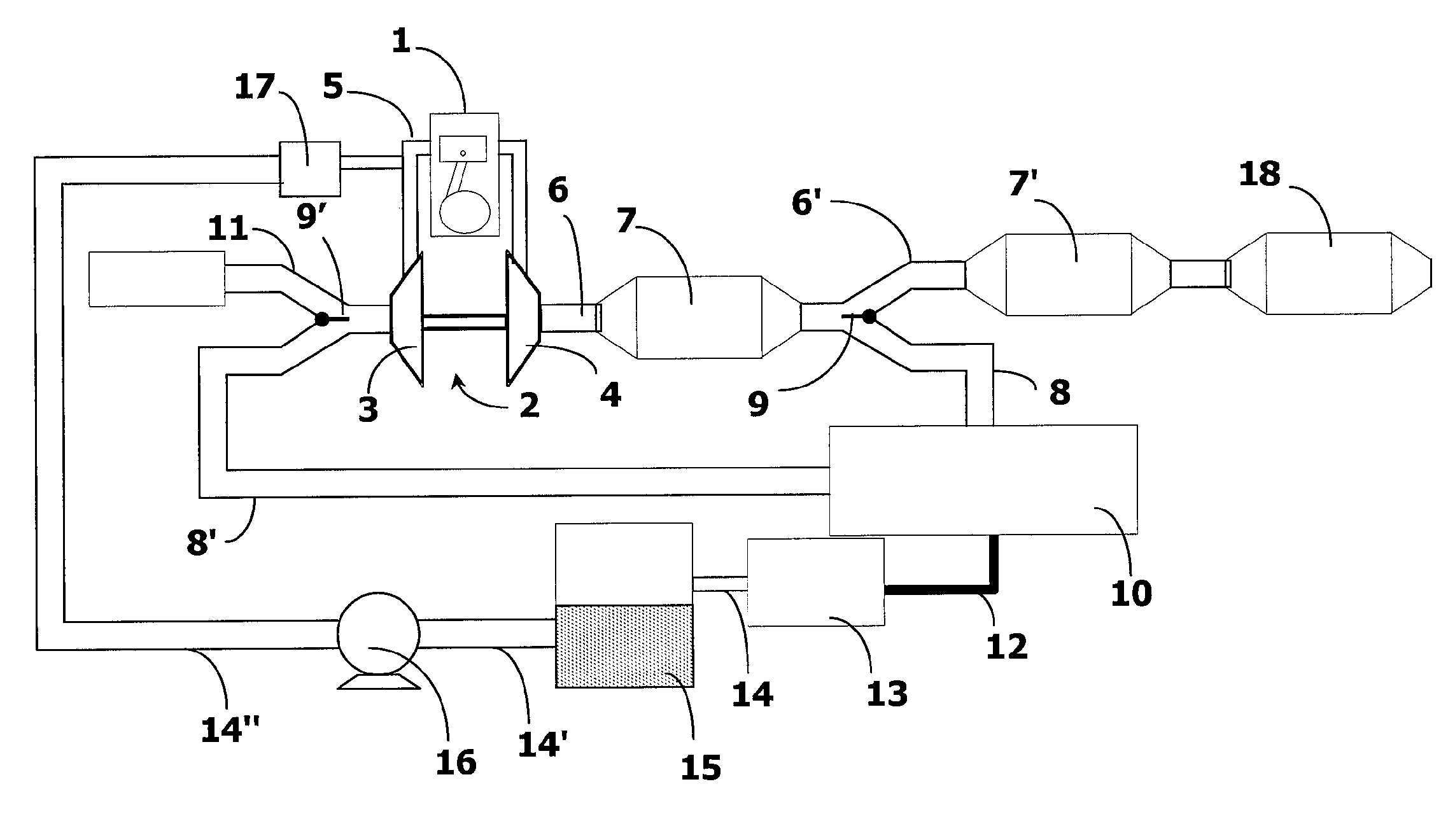
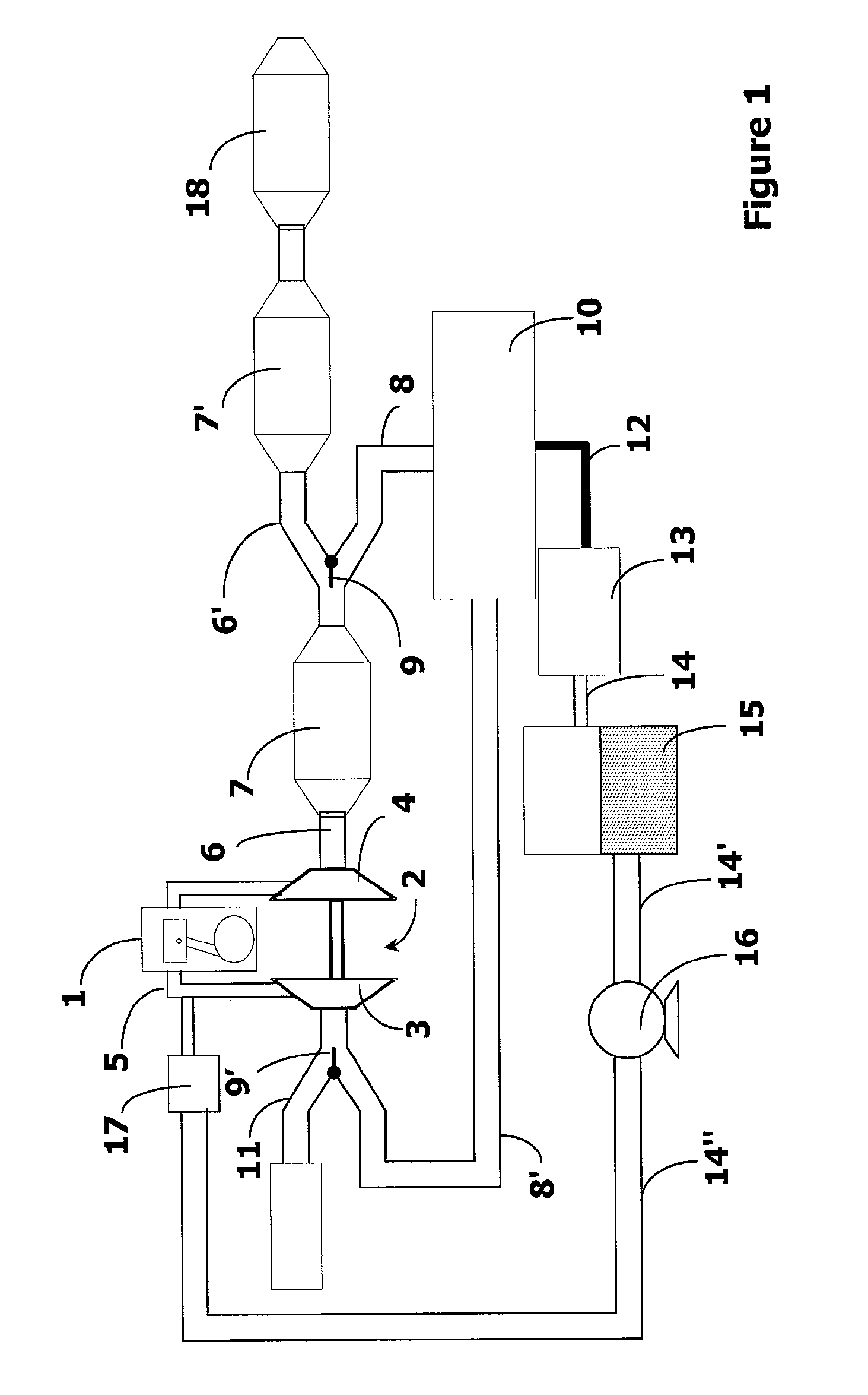
[0022]According to FIG. 1, an internal combustion engine 1, in particular a diesel engine, is provided with an exhaust-gas turbocharger 2 which has a compressor 3 and a turbine 4. The turbine 4 is traversed by the exhaust-gas flow of the internal combustion engine 1 and thereby driven. The turbine 4 drives the compressor 3, which supplies compressed charge air to the internal combustion eng...


PUM


Abstract

A system and method are disclosed for providing exhaust-gas recirculation in an internal combustion engine that has an exhaust-gas turbocharger. The exhaust gas to be recirculated is collected from the exhaust line downstream of a turbine of the turbocharger, passed through a condensate separator, and supplied into the intake line upstream of the compressor. The condensate is filtered, collected in a reservoir, and pumped to an injection device coupled to the engine intake at a location downstream of the compressor.

Description

CROSS-REFERENCE TO RELATED APPLICATIONS[0001]This application claims foreign priority benefits under 35 U.S.C. §119(a)-(d) to DE 10 2009 046 370.4 filed Nov. 4, 2009, which is hereby incorporated by reference in its entirety.BACKGROUND[0002]1. Technical Field[0003]The disclosure relates to a method and an arrangement for exhaust gas recirculation (EGR) in an internal combustion engine.[0004]2. Background Art[0005]Methods and arrangements for exhaust gas recirculation have long been used in internal combustion engines to improve efficiency and reduce emissions. In diesel engines in particular, the recirculation of exhaust gas is known for reducing particulate matter and nitrogen oxide emissions.[0006]In an internal combustion engine having a turbocharger, it is possible for exhaust gas to be extracted upstream of the turbine of the turbocharger and to be supplied to the charge air of the engine downstream of the compressor of the turbocharger, in particular downstream of the charge a...

Claims


Application Information

Patent Timeline
Patent Type & Authority Applications(United States)
IPC IPC(8): F02M25/07
CPCF01N2340/02F02M25/0222F02D41/0025F02D41/0065F02D41/1461F02M25/0709F02M25/0718F02M25/0719F02M25/0724F02M25/074Y02T10/144Y02T10/47F01N13/009F02M25/028F02B37/00F02M26/06F02M26/15F02M26/16F02M26/21F02M26/35Y02T10/12Y02T10/40
Inventor YACOUB, YASSER MOHAMED SAYED
Owner FORD GLOBAL TECH LLC
Why Eureka
Try Eureka