Manufacturing method for rod member of three-dimensional statically indeterminate truss structure

Inactive Publication Date: 2011-05-05
METAL INDS RES & DEV CENT
View PDF4 Cites 17 Cited by
  • Summary
  • Abstract
  • Description
  • Claims
  • Application Information

AI Technical Summary

Benefits of technology

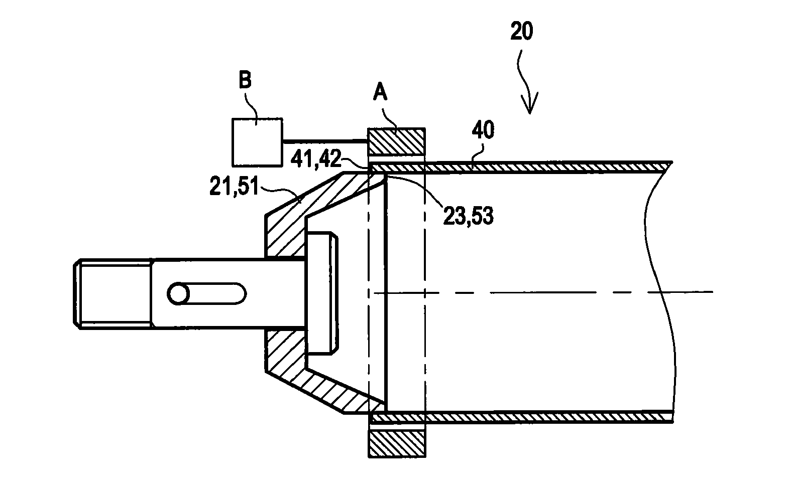
[0013]For efficacies of the present invention, the conical connection element and the tube member in the rod member of the three-dimensional truss according to the present invention are joined by applying the MPW manner, and the MPW means is environmental protective, and highly efficient (in an experiment, the welding time for the rod member is only about 56 μs), has a low power consumption, and requires no filling material. Furthermore,

Problems solved by technology

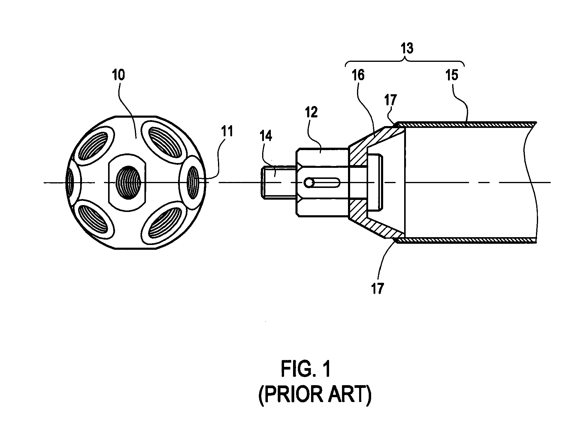
The former manner is a process which produces light harm, welding and grinding noises, and other long-term damages for eyes, skin, and human body, as well as the environment, in which a welding time is slightly long (in an experiment using a tube with an external diameter of 40 mm, the welding time is approximately 24 seconds), and it is relatively difficult to weld the above two portions together when they are made of unlike materials.
For the latter manner, the strength is rather low; more jigs are required during the mass production; a curing time is rather long (the curing ti

Method used


Image

  • Manufacturing method for rod member of three-dimensional statically indeterminate truss structure
  • Manufacturing method for rod member of three-dimensional statically indeterminate truss structure
  • Manufacturing method for rod member of three-dimensional statically indeterminate truss structure

Examples


first embodiment

[0033]FIG. 7 is a cross-sectional view of a tube member in a rod member engaged with a step portion joint of a first conical connection element or a second conical connection element according to the present invention. Referring to FIG. 7, in this embodiment, the coupling portion 23b (53b) of the first conical connection element 21b (the second conical connection element 51b) is engaged with the first end opening 41b (the second end opening 42b) of the tube member 40b in the rod member 20b by using at least one joint 70a formed on the coupling portion 23b (53b) and / or the first end opening 41b (the second end opening 42b), in which the joint 70a is an axially-extended step portion 24 (54) formed on the coupling portion 23b (53b) of the first conical connection element 21b (the second conical connection element 51b) and having an internal diameter being the same as that of the first end opening 41b (the second end opening 42b), and the first end opening 41b (the second end opening 42...

second embodiment

[0034]FIG. 8 is a cross-sectional view of a tube member in a rod member engaged with a step portion joint of a first conical connection element or a second conical connection element according to the present invention. Referring to FIG. 8, in this embodiment, the coupling portion 23c (53c) of the first conical connection element 21c (the second conical connection element 51c) is engaged with the first end opening 41c (the second end opening 42c) of the tube member 40c in the rod member 20c by using at least one joint 70b formed on the coupling portion 23c (53c) and / or the first end opening 41c (the second end opening 42c), in which the joint 70b is an axially-extended step portion 411 (421) formed on the first end opening 41c (the second end opening 42c) and having an internal diameter being the same as that of the coupling portion 23c (53c) of the first conical connection element 21c (the second conical connection element 51c), and the coupling portion 23c (53c) of the first conica...


PUM

PropertyMeasurementUnit
Diameteraaaaaaaaaa

Abstract

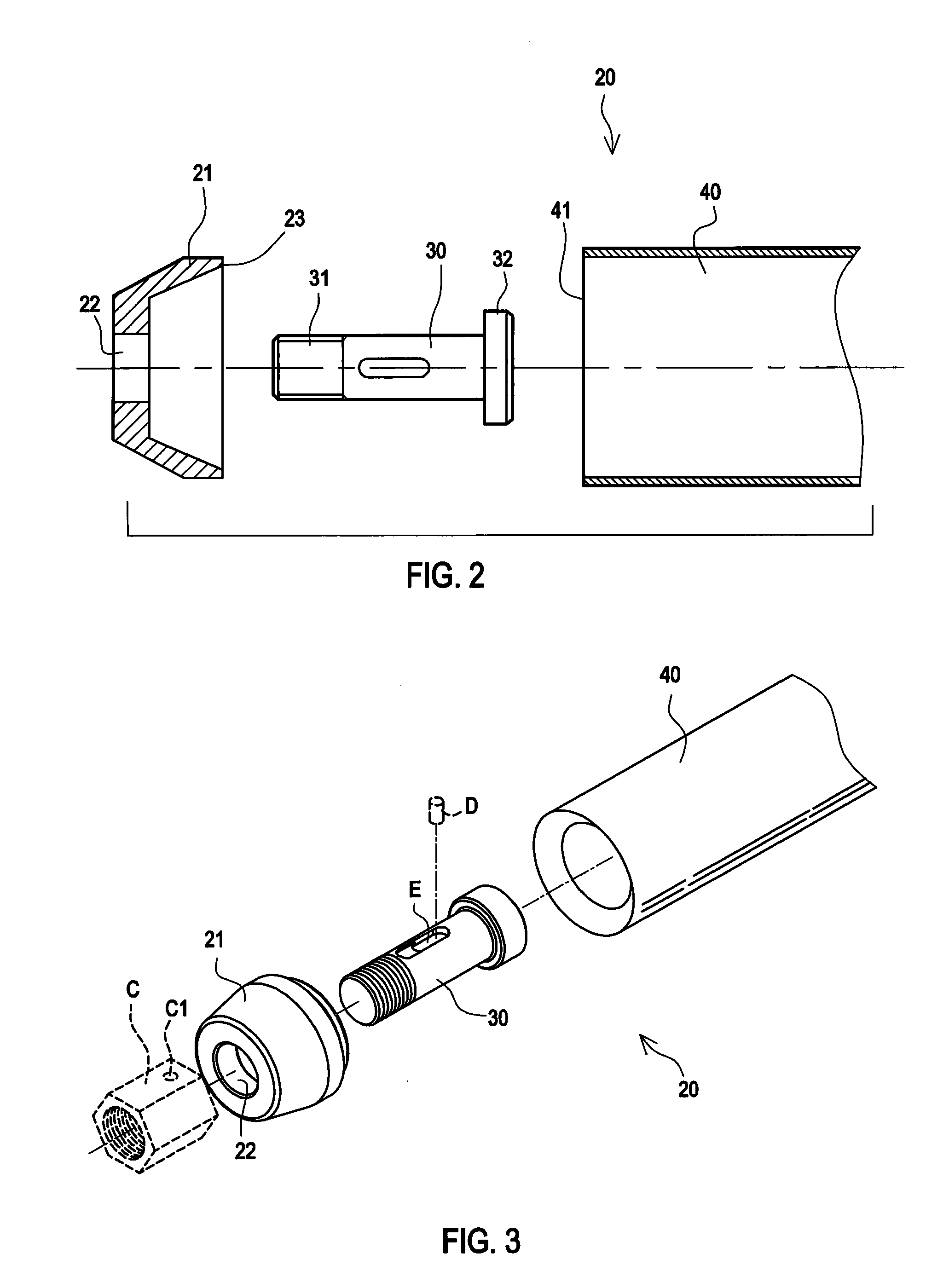
A manufacturing method for a rod member of a three-dimensional statically indeterminate truss structure is provided, which includes the following steps. A first conical connection element is provided, which has a guide slot and a coupling portion on a front and a rear end respectively. A first screw connection is made to penetrate from the coupling portion of the first conical connection element, such that a screw portion of the first screw connection penetrates out of the guide slot, and a head portion of the first screw connection is confined within the first conical connection element. The coupling portion of the first conical connection element is aligned and engaged with a first end opening of a tube member, and the first end opening of the tube member is joined to an engaging portion in the coupling portion of the first conical connection element by applying a magnetic pulse welding technique.

Description

CROSS-REFERENCE TO RELATED APPLICATION[0001]This application claims the benefit of Taiwan Patent Application No. 098137423, filed on Nov. 4, 2009, which is hereby incorporated by reference for all purposes as if fully set forth herein.BACKGROUND OF THE INVENTION[0002]1. Field of the Invention[0003]The present invention relates to a manufacturing method for a rod member of a three-dimensional statically indeterminate truss structure, and more particularly to a manufacturing method for a rod member of a three-dimensional statically indeterminate truss structure by applying a magnetic pulse welding (MPW) means.[0004]2. Related Art[0005]Since a three-dimensional truss system has been proposed by a German company “MERO” in the 1930s, amazing construction structures are created one after another by using the three-dimensional truss. In the Osaka Word Exposition in the year of 1970, the three-dimensional truss fully shows the special structural glamour. The three-dimensional truss system i...

Claims


Application Information

Patent Timeline
IPC IPC(8): B23K13/01
CPCB23K20/06
Inventor KEONG, CHI-WAHSUE, TZYY-KERHSU, HUNG-HSULIN, DIAN-YONG
Owner METAL INDS RES & DEV CENT
Why Eureka
Try Eureka