Transmission apparatus, signal sending apparatus, and signal receiving apparatus, and transmission method, signal sending method, and signal receiving method

Active Publication Date: 2011-05-05
LAPIS SEMICON CO LTD
View PDF7 Cites 4 Cited by
  • Summary
  • Abstract
  • Description
  • Claims
  • Application Information

AI Technical Summary

Benefits of technology

[0016]According to a transmission apparatus, a signal sending apparatus, and a signal receiving apparatus, and a transmission method, a signal sending method, and a signal receiving method of the present inventi

Problems solved by technology

Such a configuration produces a problem of a signal transmission method between the semiconductor chip and the FPGA.
Since the operation clock frequency of the semiconductor chip is typically different from the operation clock frequency of the FPGA, it is problematic that a receiving flip-flop oscillates (a so-called metastable phenomenon occurs) depending on signal acquisition timing on the reception side.
That is, if a signal level is changed at the timing of signal acquisition by the receiving flip-flop, it is not determined whether the signal level is high or low, resulting in oscillation of the receiving flip-flop.
However, such a conventional metastability measure circuit has the following problems.
A first problem is that a control signal pulse is unable to be received correctly on the reception side.
In this c

Method used


Image

  • Transmission apparatus, signal sending apparatus, and signal receiving apparatus, and transmission method, signal sending method, and signal receiving method
  • Transmission apparatus, signal sending apparatus, and signal receiving apparatus, and transmission method, signal sending method, and signal receiving method
  • Transmission apparatus, signal sending apparatus, and signal receiving apparatus, and transmission method, signal sending method, and signal receiving method

Examples


Embodiment Construction

[0026]Exemplary embodiments of the present invention will now be described with reference to the accompanying drawings.

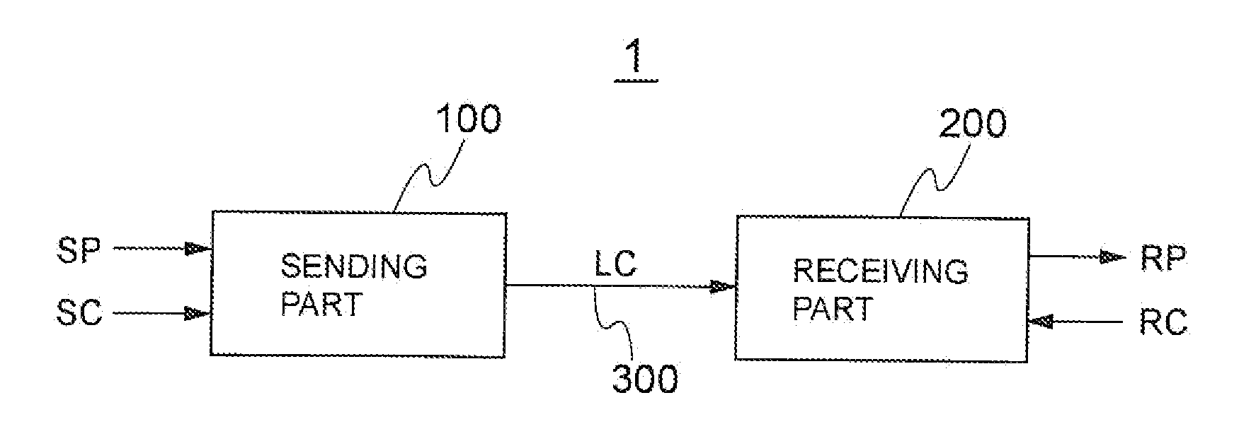
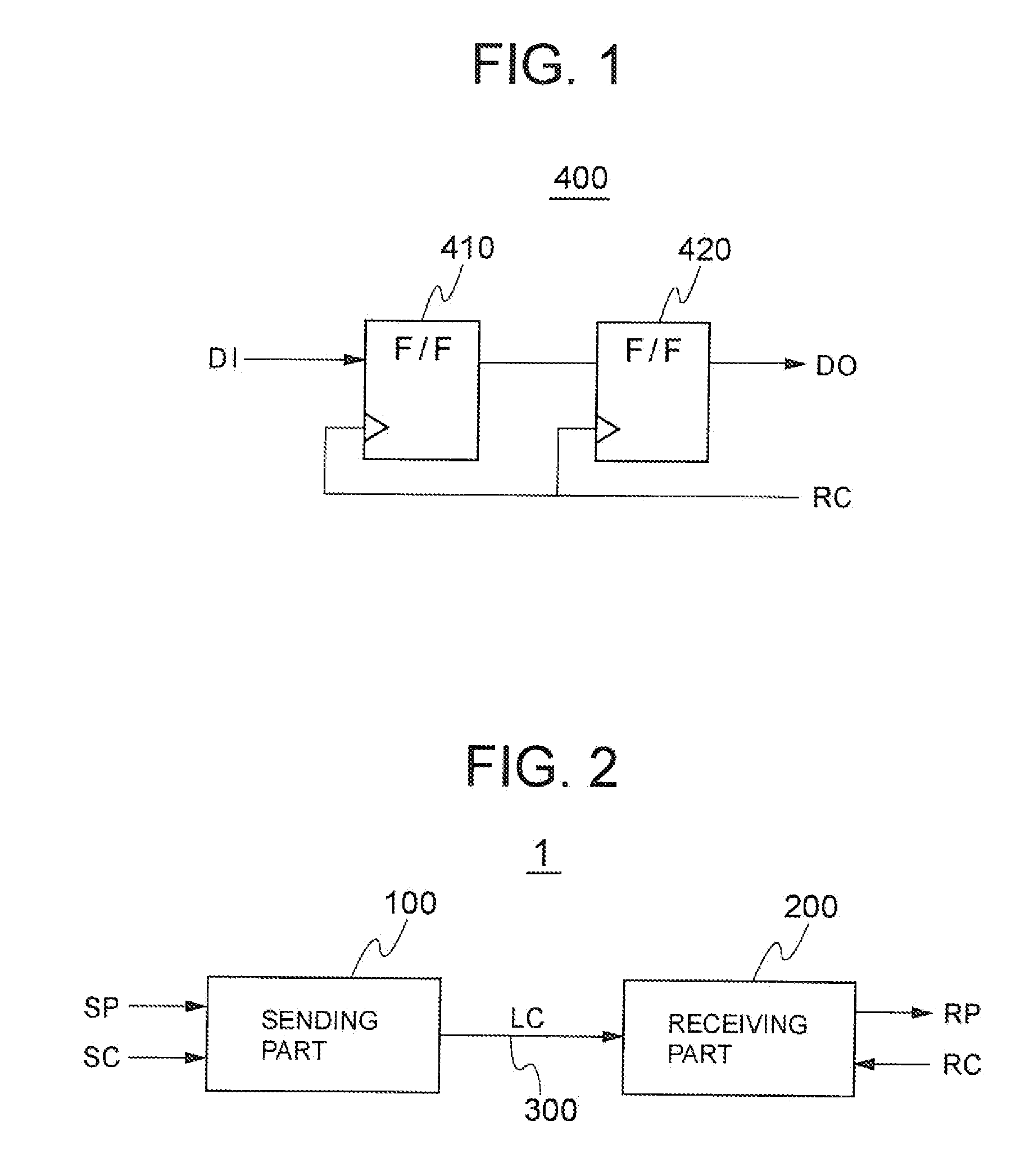
[0027]FIG. 2 is a block diagram of a transmission apparatus 1 of an embodiment. The transmission apparatus 1 includes a sending part 100 and a receiving part 200. The transmission apparatus 1 is mounted on a single printed circuit board or module printed circuit board (not depicted) included in an apparatus such as a personal computer or a server, for example, and sends a transmission signal LC from the sending part 100 to the receiving part 200 via a transmission path 300 consisting of conductive wiring made of, for example, copper formed in the printed circuit board. The sending part 100 and the receiving part 200 may be mounted as a signal sending apparatus 100 and a signal receiving apparatus 200 on their respective module circuit boards (not depicted).

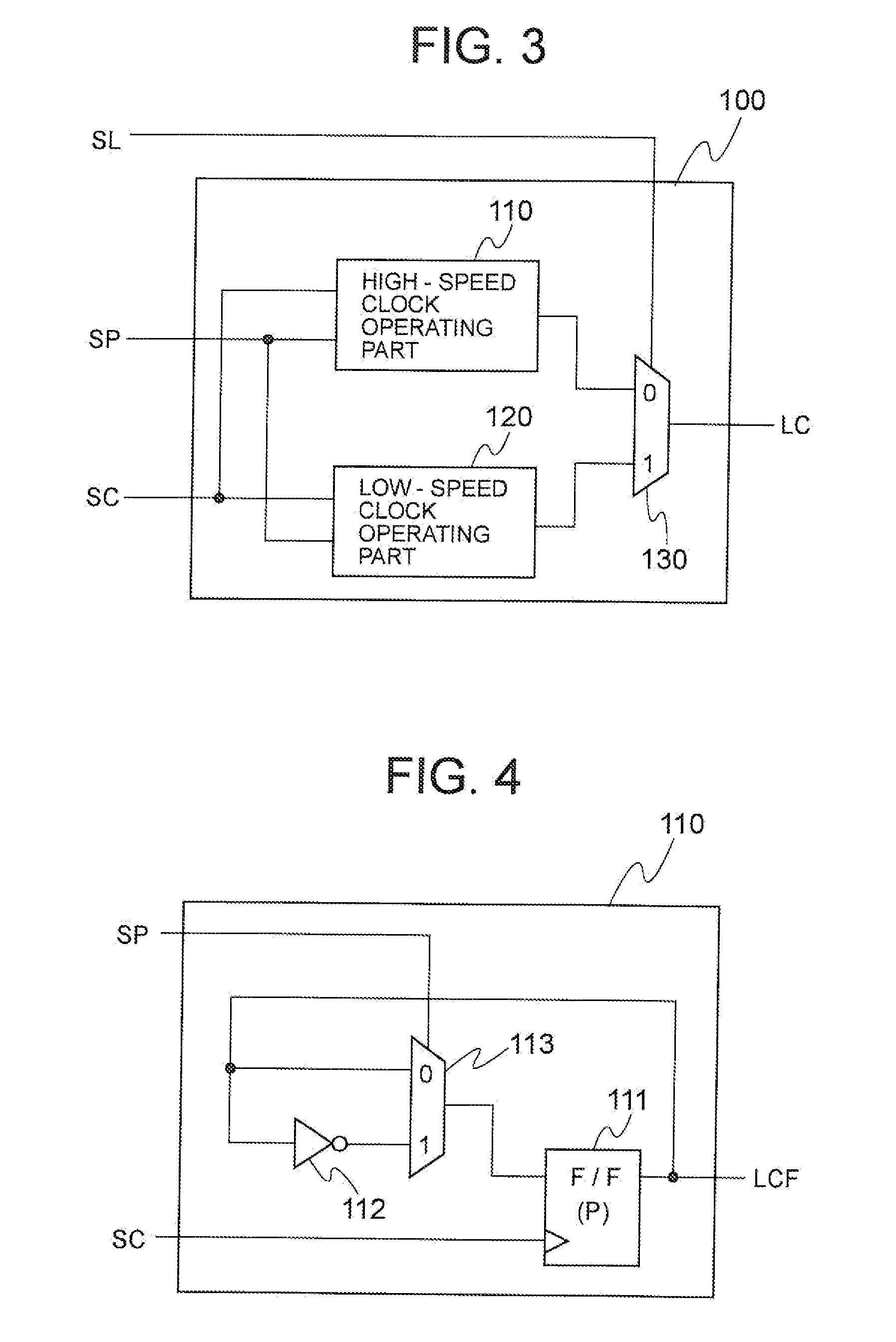
[0028]The sending part 100 operates in synchronization with a sending clock SC (first clock) having a first per...


PUM


Abstract

A transmission apparatus, a signal sending apparatus, and a signal receiving apparatus, and a transmission method, a signal sending method, and a signal receiving method capable of solving a problem of metastability and suppressing a delay of a signal when sending and receiving apparatuses having different operation clock frequencies send/receive the signal representative of control information, for example. Included are a sending part that operates in synchronization with a first clock having a first period to output a transmission signal having a signal level that is inverted in response to an input of a first pulse signal corresponding to the first period and a receiving part that operates in synchronization with a second clock having a second period to output a second pulse signal corresponding to the second period in response to inversion of a signal level of the transmission signal.

Description

BACKGROUND OF THE INVENTION[0001]1. Field of the Invention[0002]The present invention relates to a transmission apparatus, a signal sending apparatus, and a signal receiving apparatus, and a transmission method, a signal sending method, and a signal receiving method having a so-called metastability measure.[0003]2. Description of the Related Art[0004]An apparatus such as, for example, a personal computer or a server often employs a configuration with a circuit responsible for general-purpose operations incorporated into a semiconductor chip and a circuit specific to each user incorporated into FPGA (field programmable gate array) such that the apparatus is operated by mutually sending and receiving signals between the semiconductor chip and the FPGA from a cost standpoint.[0005]Such a configuration produces a problem of a signal transmission method between the semiconductor chip and the FPGA. Since the operation clock frequency of the semiconductor chip is typically different from t...

Claims


Application Information

Patent Timeline
IPC IPC(8): H04L7/02H04L27/00
CPCH04L7/0337H04L7/0091
Inventor UEHARA, TERUAKI
Owner LAPIS SEMICON CO LTD
Why Eureka
Try Eureka