Tool for minimally invasive surgery
- Summary
- Abstract
- Description
- Claims
- Application Information
AI Technical Summary
Benefits of technology
Problems solved by technology
Method used
Image

Examples
embodiment i
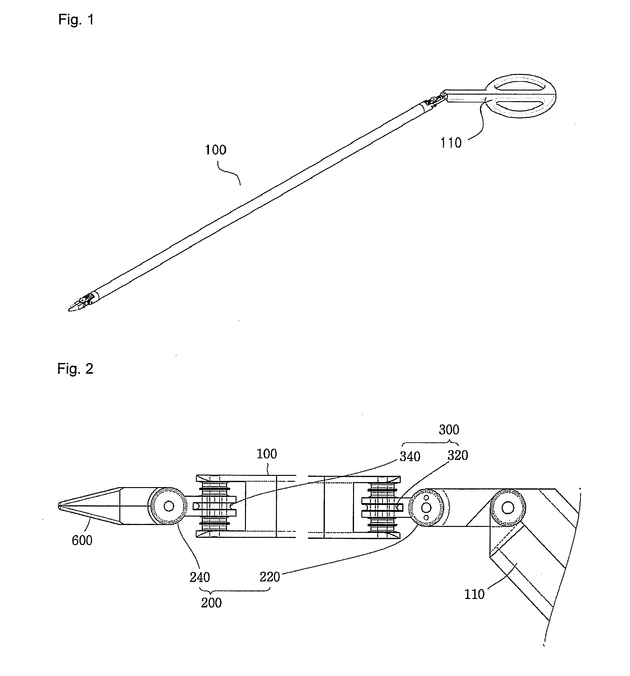
FIG. 1 is a perspective view showing the outer appearance of a tool 1 for minimally invasive surgery, in accordance with a first embodiment of the present invention. Referring to FIG. 1, the tool 1 for minimally invasive surgery includes an elongated shaft 100 of a predetermined length, which has one or plural spaces inside (e.g., pipe-shape, lotus-shaped, or spiral-shaped space), and an adjustment handle 110.
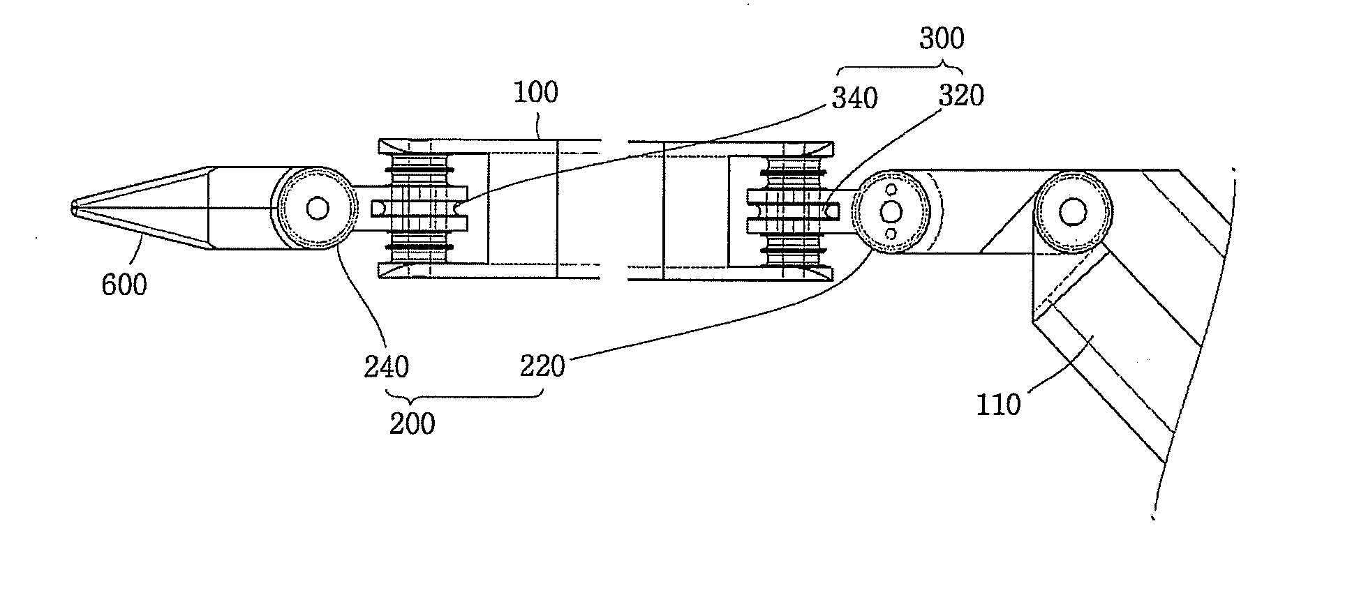
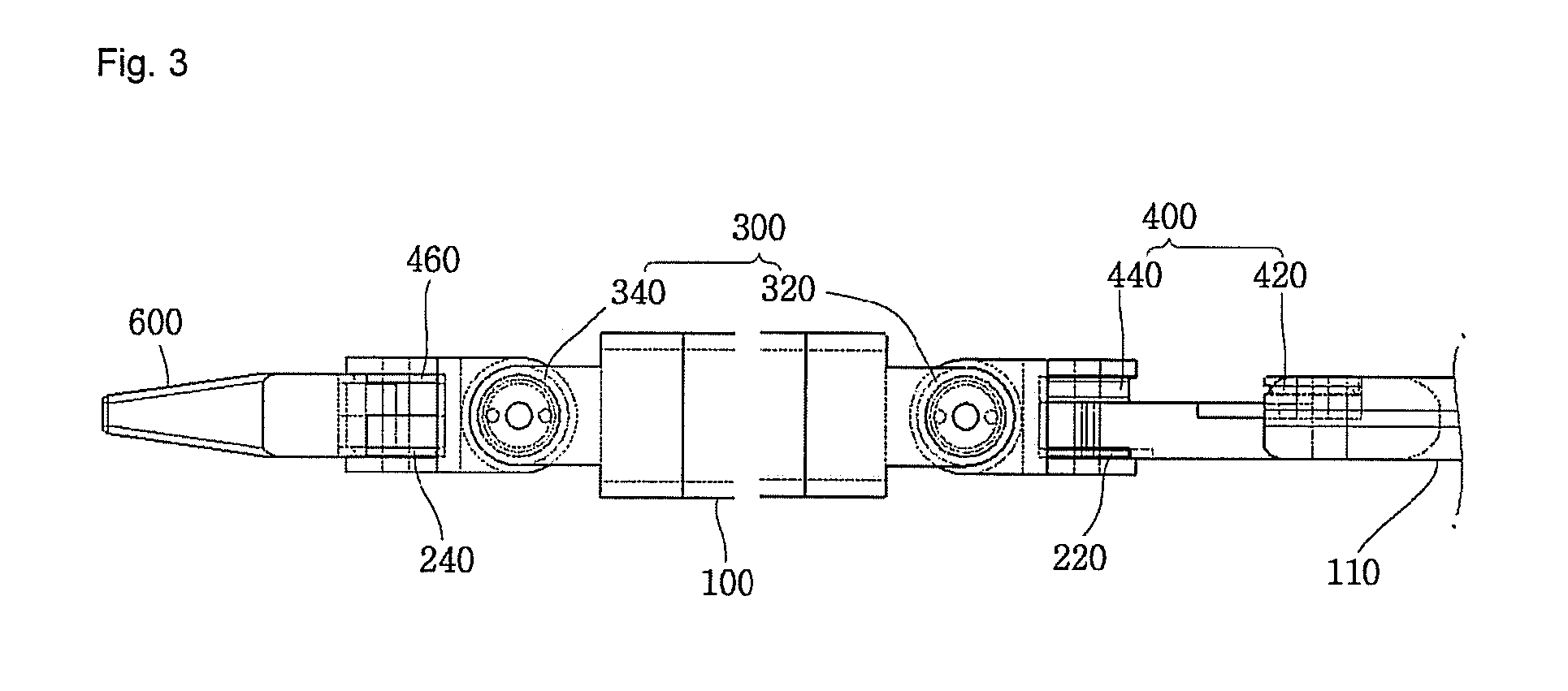
FIG. 2 is a side view showing a detailed configuration of main elements such as a pitch axis part 200 and a yaw axis part 300 in accordance with a first embodiment of the present invention, and FIG. 3 is a plan view showing a configuration of main elements as a yaw axis part 300 in accordance with the first embodiment of the present invention.
As shown in FIGS. 2 and 3, a tool 1 for minimally invasive surgery in accordance with the first embodiment of the present invention includes an elongated shaft 100, and an adjustment handle 110 and an end effector 600 disposed on both ends...
embodiment ii
Unlike the first embodiment of the present invention discussed above which suggested the tool 1 for minimally invasive surgery utilizing the opening and closing end effector 600, a tool for minimally invasive surgery which does not always absolutely require the opening and closing operation may be addressed. For instance, a hook electrode used for the end effector may be addressed.
FIG. 18 is a perspective view showing the outer appearance of a tool for minimally invasive surgery in accordance with a second embodiment of the present invention, and FIGS. 19 and 20 show a detailed view of ‘A’ part and ‘B’ part in FIG. 18.
Referring to FIGS. 18 to 20, an adjustment handle 110A for controlling the operation of an end effector 600A in hook-electrode form is connected to one end of an elongated shaft 100 by a first axis connection part 500A, and the end effector 600A is connected to the other end of the elongated shaft 100 by a second axis connection part 500B. Unlike the first embodiment, ...
embodiment iii
Referring next to FIGS. 23 to 26, a third embodiment of the present invention in which an end effector 600B operates as two rods 114A and 114B that constitute an adjustment handle 110B operate concurrently will be discussed.
FIG. 23 is a perspective view showing the configuration of the adjustment handle 110B used for a tool for minimally invasive surgery in accordance with the third embodiment of the present invention, and FIG. 24 is a detailed view of ‘A’ part in FIG. 23.
To configure the adjustment handle 110B disposed on one end of the elongated shaft 100, one ends of the first and the second rods 114A and 114B are connected to each other by a rotation axis, and two enclosures 114C of a semi-circular shape are formed symmetrically to each other on one side of each of the first and the second rods 110A and 110B. Also, first and second cable pulleys 222A and 422A are positioned on either side of the rotation axis that connects the first rod 114A with the second rod 114B. Here, the f...
PUM
 Abstract
Description
Claims
Application Information
 - Generate Ideas
- Intellectual Property
- Life Sciences
- Materials
- Tech Scout
- Unparalleled Data Quality
- Higher Quality Content
- 60% Fewer Hallucinations
Browse by: Latest US Patents, China's latest patents, Technical Efficacy Thesaurus, Application Domain, Technology Topic, Popular Technical Reports.
© 2025 PatSnap. All rights reserved.Legal|Privacy policy|Modern Slavery Act Transparency Statement|Sitemap|About US| Contact US: help@patsnap.com