Wind tunnel aircraft model with truncated wing

a wind tunnel and aircraft model technology, applied in the field of aircraft scaled models, can solve the problems of difficult scaling of results, loss of upstream dynamic pressure, and difficulty in obtaining comprehensive analytical models of aerodynamic behaviour, and achieve the effect of increasing the maximum scale of aircraft models and increasing the number of reynolds

Inactive Publication Date: 2011-05-05
AIRBUS OPERATIONS SL
View PDF5 Cites 9 Cited by
  • Summary
  • Abstract
  • Description
  • Claims
  • Application Information

AI Technical Summary

Benefits of technology

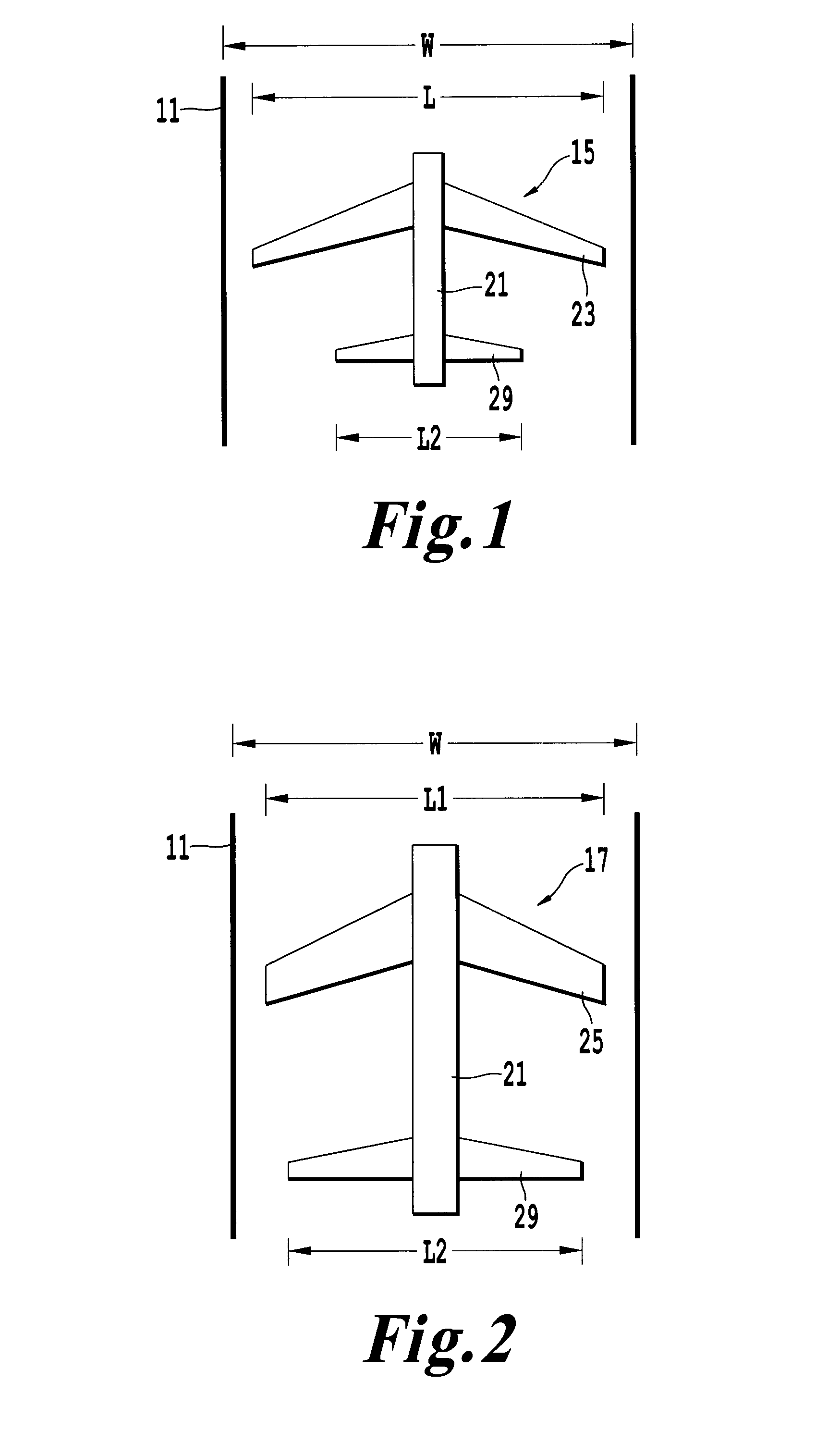
[0007]It is an object of the present invention to provide a wing design methodology that, starting from one available reference wing in an aircraft model develops a different twisted and truncated wing with smaller span, that allows to increase the maximum scale of the aircraft model producing a higher Reynolds number during wind tunnel tests as, in this way, the size of the aircraft model wing will not be the part which limits the scale of the model.
[0008]It is another object of the present invention to provide an aircraft model for wind tunnel testing that allows improving the results obtained in flow investigations around tails and rear fuselage.
[0009]It is another object of the present invention to provide an aircraft model for wind tunnel testing that allows optimizing the costs of flow investigations around tails and rear fuselage.
[0010]It is another object of the present invention to provide an aircraft model having a truncated wing that allows reproducing in the aircraft model rear part the flow conditions produced by the reference wing.
[0011]It is another object of the present invention to provide an aircraft model which allows to test the rear part of the aircraft at the maximum Reynolds number allowed, limited only by the size of the aircraft tails and rear parts.
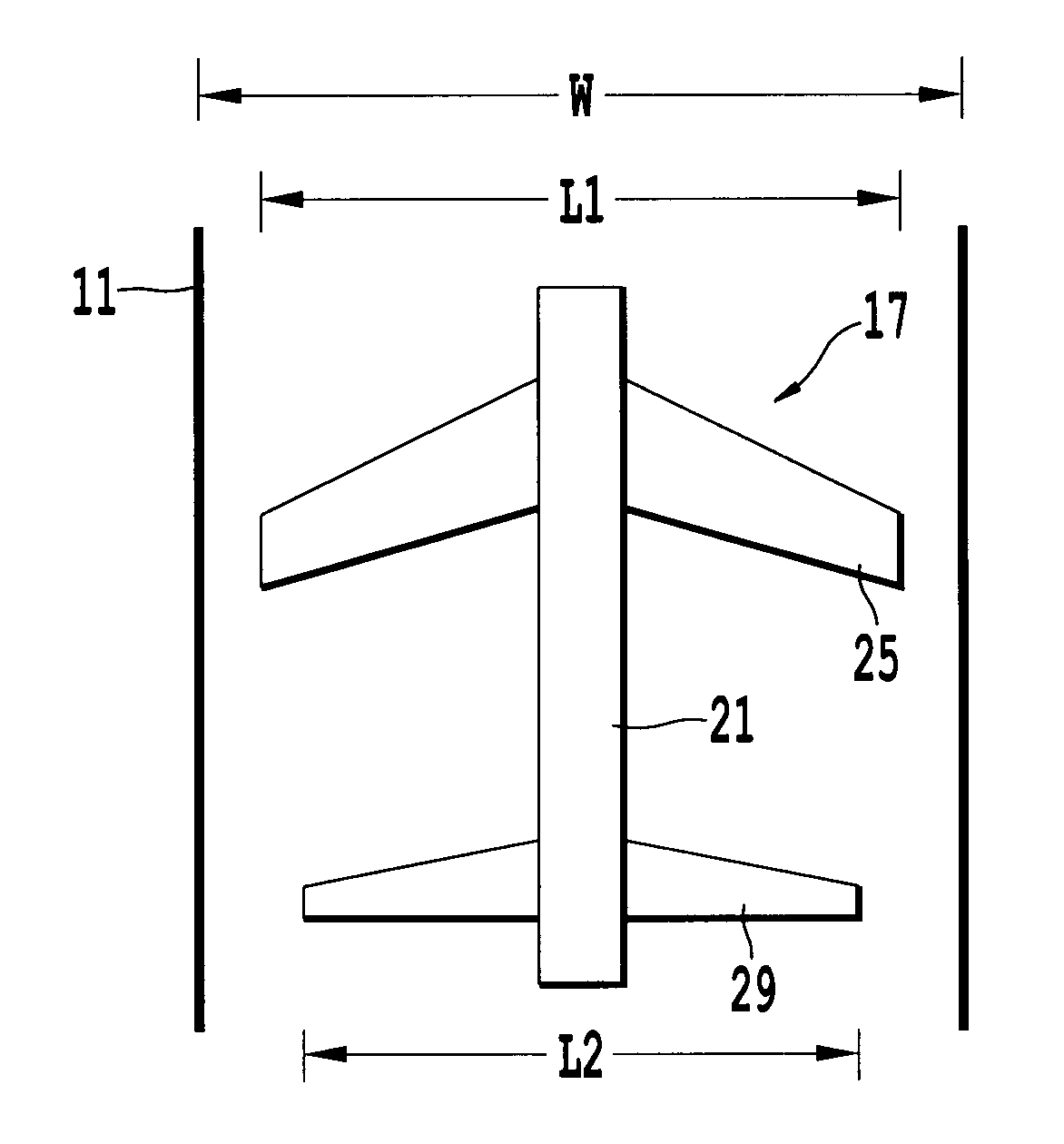
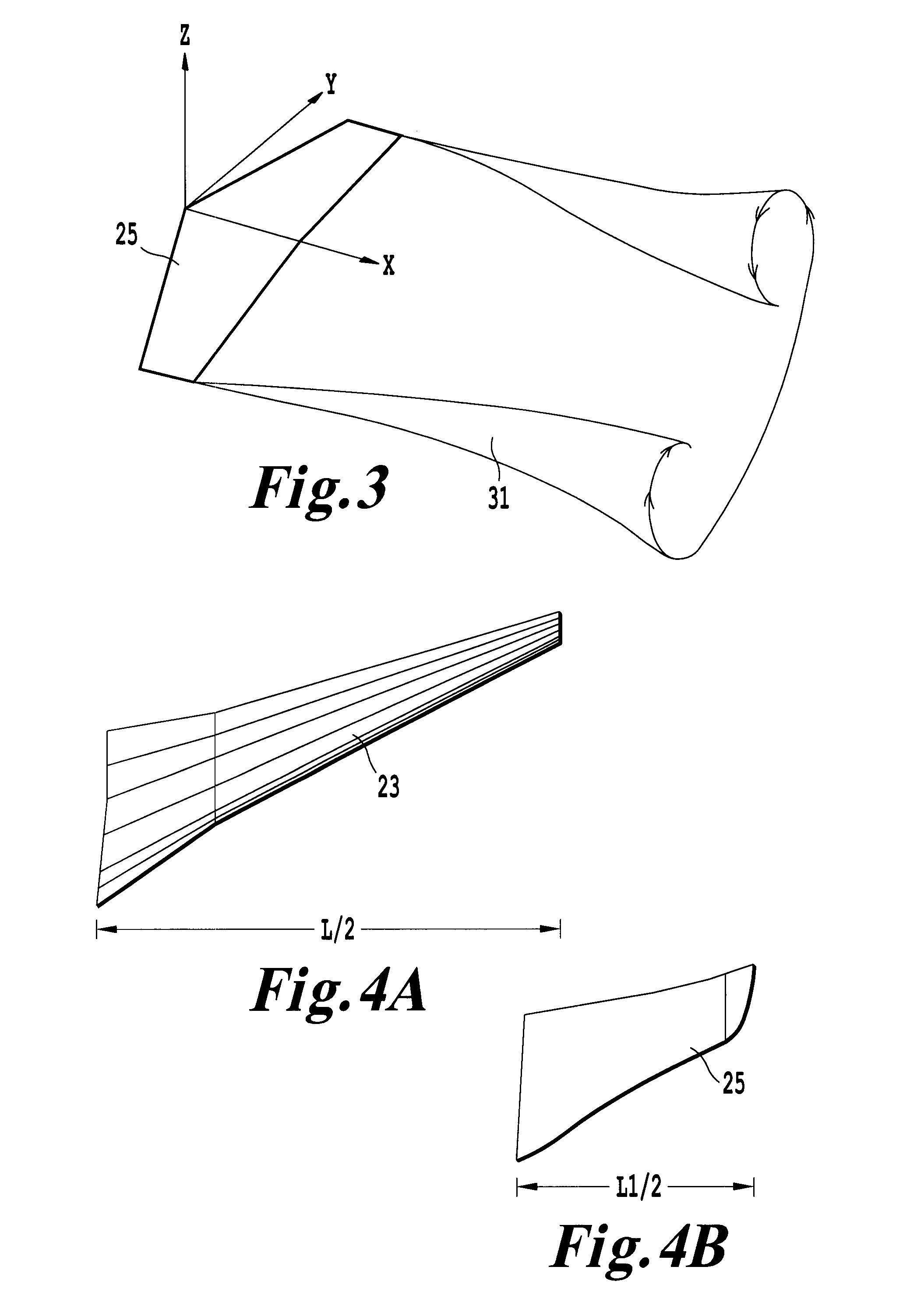
[0019]In a preferred embodiment, said truncated wing geometry produces a similar lift distribution than the one produced by the full span model wing along at least the maximum length L2 in the Y-axis of any component in the rear aircraft. Hereby, it is achieved an aircraft model as large as possible in the rear aircraft for improving the results of wind tunnel data.

Problems solved by technology

The performance of aircraft mobile surfaces such as vertical tails, horizontal tail planes, elevators or rudders placed in the rear part of the aircraft is one of the more important issues in global aircraft design.
Those tests are particularly important for the rear part of the aircraft because it is difficult to obtain comprehensive analytical models of its aerodynamic behaviour since the rear part of the aircraft is affected by other parts of an aircraft and particularly by the aircraft wing.
For example they can suffer a loss of upstream dynamic pressure due to effects caused by the wing which is difficult to take into account using classical analytical schemes.
Even though the results currently obtained in wind tunnel tests allow a good understanding of the aerodynamical behaviour of tails and other components of the rear part of the aircraft, they are usually produced at a Reynolds number very much lower than the real aircraft flight Reynolds number and therefore the scaling of the results is sometimes difficult.

Method used


Image

  • Wind tunnel aircraft model with truncated wing
  • Wind tunnel aircraft model with truncated wing
  • Wind tunnel aircraft model with truncated wing

Examples


Embodiment Construction

[0026]Nowadays the design of aircrafts is done using Computational Fluid Dynamics (CFD) and Wind Tunnel Testing (WTT).

[0027]Wind tunnels are installations in which the aerodynamic behaviour of a scaled model of a proposed aircraft can be analysed. They are structures in which wind is produced, usually by a large fan, where the flow passes through one scaled model which is connected to instruments that measure and record the airflow around it and the aerodynamic forces that act upon it. The information obtained in wind tunnels is used for characterising the behaviour of the aircraft model under different flow conditions and therefore allows improving its design.

[0028]The aircraft model is placed in the wind tunnel with a suitable instrumentation to provide the required data. To obtain meaningful data, the flow parameters of Mach number and Reynolds number in the wind tunnel shall match the real aircraft flight conditions.

[0029]The Reynolds number expresses the ratio of inertial (resi...


PUM


Abstract

An aircraft model (17) for testing in a wind tunnel (11) of width W comprising a fuselage (21), a truncated wing (25) whose length L1 is lesser than the length L of a full scaled wing (23) and additional components in the rear aircraft as, in particular, an horizontal tail plane (29), that produces the same downwash arriving to said additional components than in a full scaled model. The shape of said truncated wing (25) may be designed for having a similar lift distribution (35) to the lift distribution (37) of a full scaled wing (23) along at least the maximum length L2 in the Y-axis of any component in the rear aircraft. The invention also relates to a method for designing said truncated wing (25).

Description

FIELD OF THE INVENTION[0001]The present invention refers to aircraft scaled models used in wind tunnels for analysing its aerodynamic properties and more particularly to aircraft scaled models for analysing the aerodynamic properties of the aircraft tails and rear fuselage.BACKGROUND OF THE INVENTION[0002]The performance of aircraft mobile surfaces such as vertical tails, horizontal tail planes, elevators or rudders placed in the rear part of the aircraft is one of the more important issues in global aircraft design. Said surfaces are used as control surfaces, for example a horizontal tail plane is used to control pitch and a rudder is used to control yaw. Therefore its behavior defines aircraft control laws and design constrains.[0003]When designing the elements composing an aircraft, such as the fuselage, wings, stabilizers, etc. it is necessary to know the aerodynamic properties of such components. In view of the large size of aircrafts, aerodynamic tests are made with scaled mod...

Claims


Application Information

Patent Timeline
Patent Type & Authority Applications(United States)
IPC IPC(8): G06F17/50B64C3/10
CPCG01M9/08
Inventor GARRIDO, ESTEBAN AMOORGE, PILAR VELAFUERTES, ANGEL PASCUAL
Owner AIRBUS OPERATIONS SL
Why Eureka
Try Eureka