Detection Device for Fluid Sample

a detection device and fluid sample technology, applied in the field of detection devices, can solve the problems that liquid in the test strip groove is not easy to enter the liquid storage chamber, and achieve the effects of improving safety, simple operation, and less influence on the surrounding environmen

Inactive Publication Date: 2011-05-12
HANGZHOU DITU TECH +2
View PDF5 Cites 18 Cited by
  • Summary
  • Abstract
  • Description
  • Claims
  • Application Information

AI Technical Summary

Benefits of technology

[0028]Therefore, the present invention is characterized by its simple operation, airtight and irreversible sealing, less influence by surrounding environment, improved safety for operators and less requirement for the quantity of liquid samples. The interior of the device only comprises two chambers of which one chamber only communicates with the other chamber for collecting and storing liquid sample. Before testing, the liquid in the liquid storage chamber holds still only by means of liquid tension and the air pressure in said chamber. Only when the plunger element attached in cup lid press

Problems solved by technology

Since the lid seals the opening of the cup tightly, the liquid in the liquid storage chamber can only enter into the test strip groove

Method used


Image

  • Detection Device for Fluid Sample
  • Detection Device for Fluid Sample
  • Detection Device for Fluid Sample

Examples


example 1

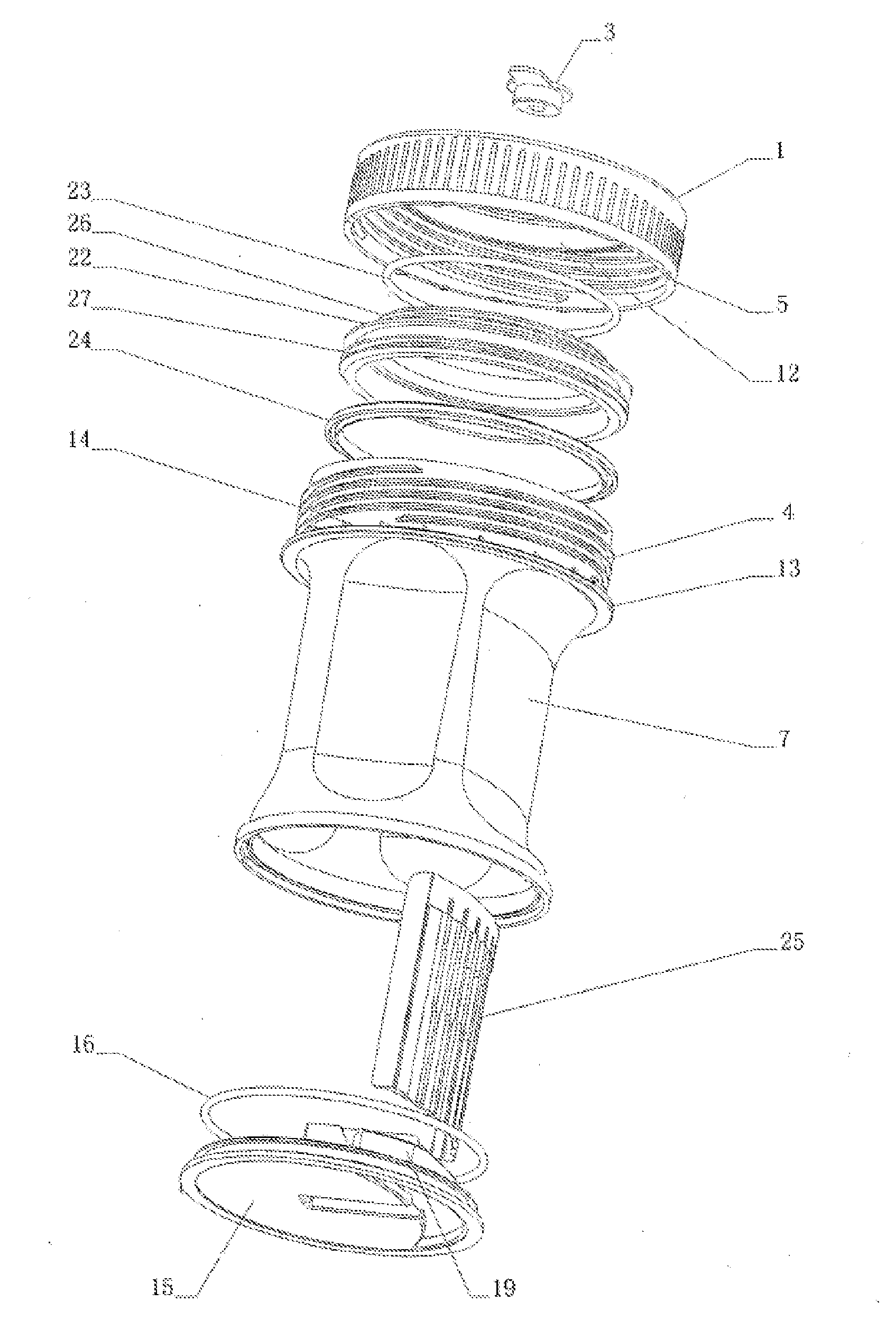
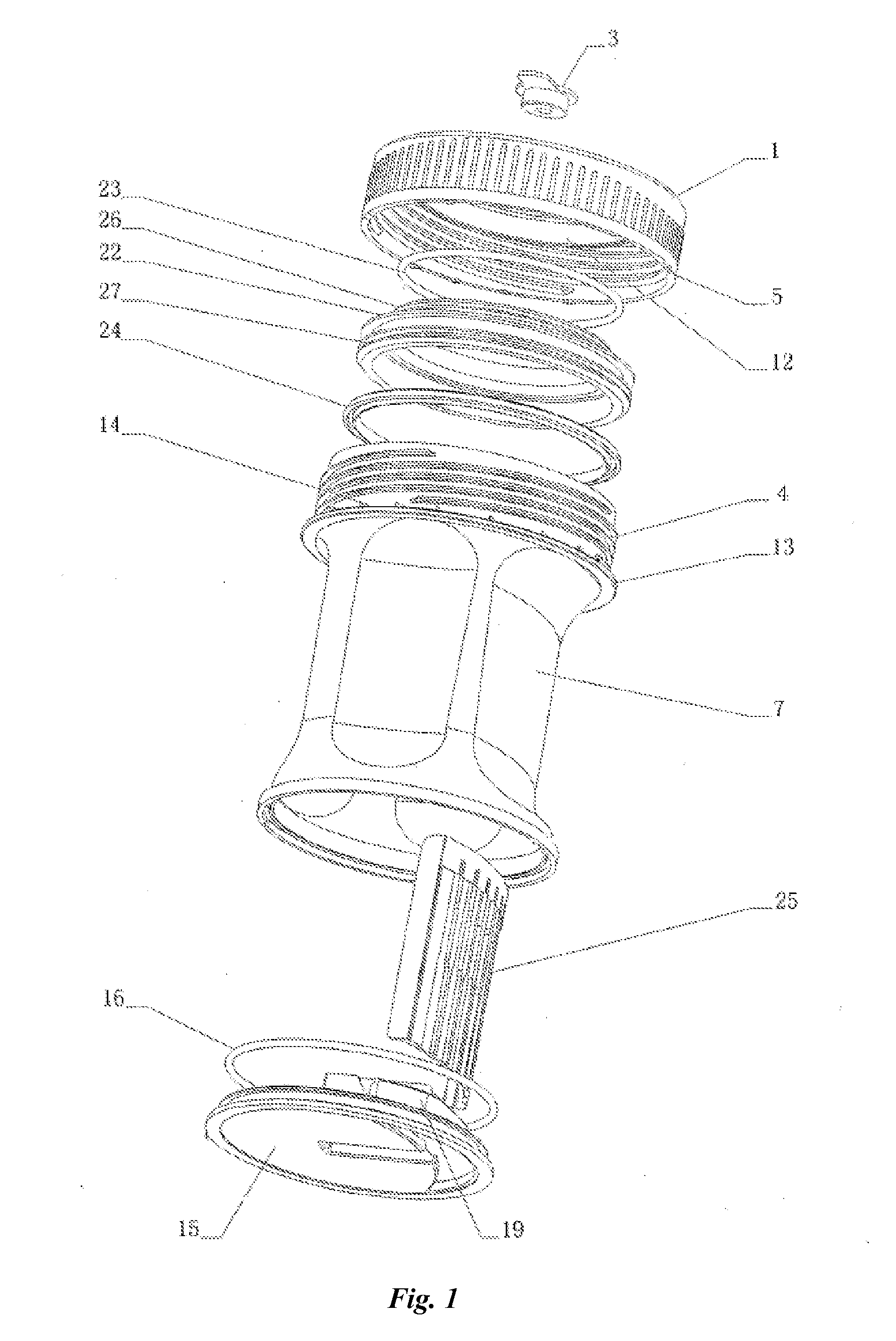
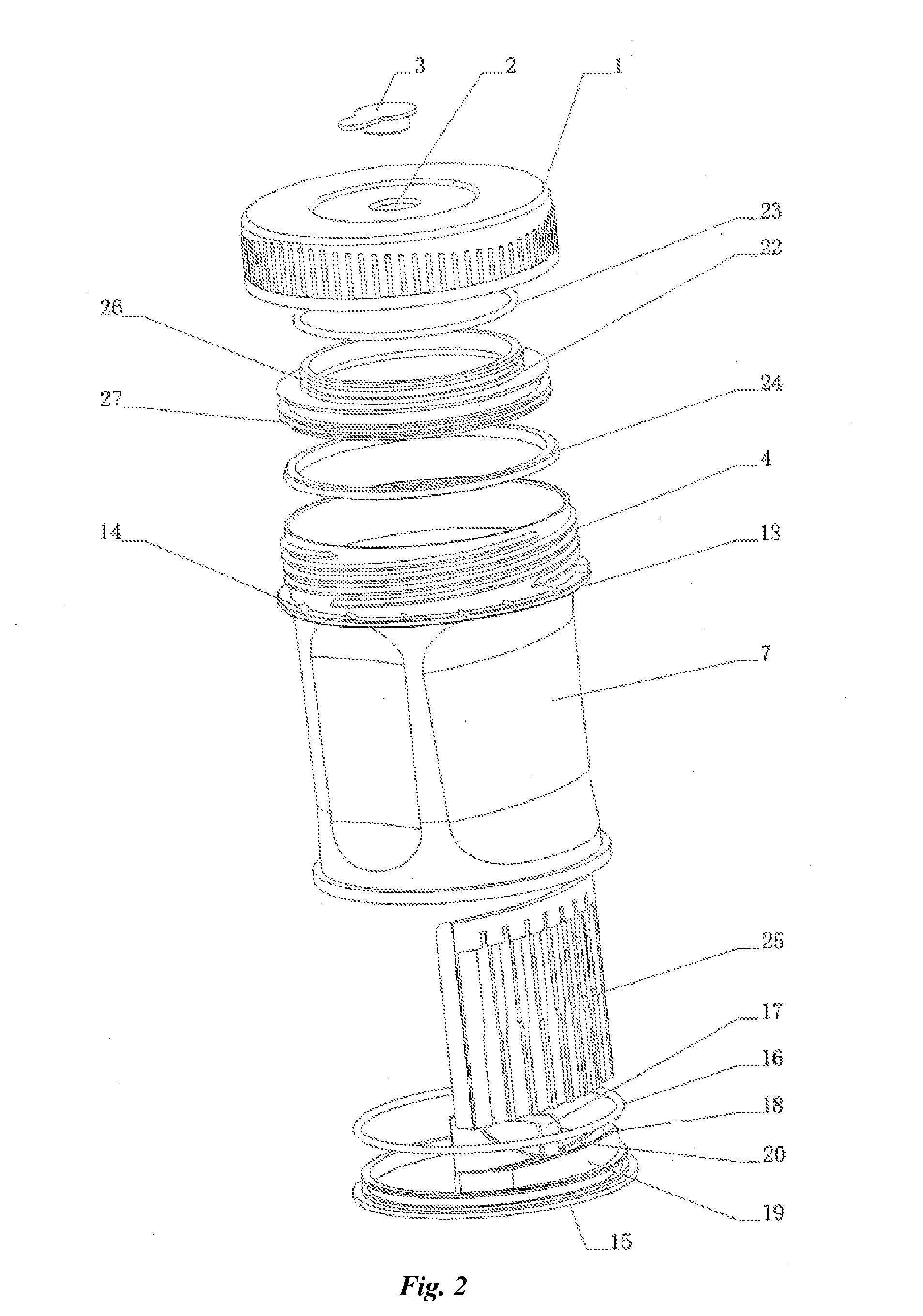
[0040]The first Example of the present invention is shown in FIG. 1 and FIG. 2. The device for detecting analytes in fluid samples comprises a lid 1, a cup body 7, a test strip plate 25 and a base 15. Inside the lid 1 is provided a plunger element 22 that is hermetically coupled to the lid 1 by a circular piston seat 12 inside the lid 1. The plunger element 22, also in circular form, has a zigzag cross section (Z-shape), a connecting end 26 and a working end 27 as shown in FIG. 3 and FIG. 5. The outer diameter of connecting end 26 is less than that of working end 27. Meanwhile the outer diameter of connecting end 26 is less than that of inner diameter of piston seat 12. The connecting end 26 is hermetically coupled to the inside of piston seat 12 by a connecting seal ring 23 that has a circular cross section. As shown in FIG. 4, the lid 1 is provided with a liquid-taking port I2 communicating with the area where the plunger element 12 lies in. The lid 1 is provided with a groove in ...

example 2

[0045]FIG. 4 is a schematic view of an assembled structure of the lid according to the present invention. FIG. 6 is a schematic view of an assembled structure according to the present invention. The structures of the cup body 7, the base 15 and the test strip plate 25 are all the same as Example 1 except that the lid 1 is provided with a piston-mounting port 6. As shown in FIG. 4 and FIG. 6, the piston-mounting port 6 has the same diameter as that of an interior of piston seat 12. After mounting to a piston 22, place connecting end 26 in piston-mounting port 6 in the outside of the lid 1. A connecting end 26 is hermetically coupled to the interior of the piston seat 12 by two longitudinally mounted connecting seal rings 23 that has a circular cross section. The piston 22 is provided with a tear strip 32 at the connecting end 26 in the exterior of the lid 1.

[0046]A tear strip 32 is fixedly connected with the piston 22 and increases the perimetric size of the piston 22 so that the pis...

example 3

[0049]FIG. 7 and FIG. 8 are schematic views of an assembled structure respectively according to the present invention, and FIG. 9 is a schematic view of an assembled structure of a test strip plate according to the present invention. The Example 3 contains cup body 7 with a sealing lid 1 on its tip by thread connection. The cup body and sealing lid are coupled with thread. The cup is provided with a bulge loop below the thread and the bulge loop is provided with two wedge-shaped bulges 38 while there are two wedge-shaped bulges corresponding to the above-mentioned wedge-shaped bulges respectively below the seal lid but with opposite directions of the wedge-shaped bulges' high surfaces. The cup body is provided with a testing plate slot 36 in the test strip plate at ¼ height at one side. The slot communicates with the cup body. The slot is provided with a sealing layer to separate inner space with the outside. The bottom of cup body is closely coupled with a base 6. The mouth of the ...


PUM


Abstract

This invention provides a device for detecting an analyte in a liquid sample, comprising a cup body (7), a lid (1) and a base (15), wherein, said the cup body (7) comprises a liquid storage chamber (9) and a test strip groove locating in one side of liquid storage chamber, the storage chamber (9) and the test strip groove communicates each other through a small hole in the bottom of liquid storage chamber, the test strip groove is configured with a test strip plate, said lid being able to seal the opening of the cup tightly, said opening of cup being directly connected with the liquid storage chamber.

Description

FIELD OF THE INVENTION[0001]The present invention relates to a device for detecting analytes in fluid samples, particularly to a device for detecting liquid samples easily and sanitarily.DESCRIPTION OF THE PRIOR ART[0002]In the fields of medicine, criminal investigation and competitive sports, detection of liquid, particularly urine, is very common, since the compositions in the urine usually represent various symptoms of human body and helps to judge the compositions of food that people ate. Therefore, detection of urine is helpful to medical treatment, criminal investigation and fair competitive sports. Common detection methods of liquid sample use chromatographic analysis to detect the presence of specific “marks” in the liquid. The marks are different colors represented on the test strips. According to different colors, one can judge the types and quantities of the compositions contained in the liquid. In practice, operators usually collect a specific quantity of liquid (mainly ...

Claims


Application Information

Patent Timeline
IPC IPC(8): G01N1/10
CPCA61B10/0045A61B10/007B01L3/5023B01L2300/0864B01L2300/0663B01L2300/0825B01L2300/0838B01L2300/044
Inventor LV, XINLONG
Owner HANGZHOU DITU TECH
Why Eureka
Try Eureka