Two- or multi-layer ferrelectret and method for the production thereof

a ferrelectret and multi-layer technology, applied in the direction of device details, fixed capacitor details, device details, etc., can solve the problems of current flow between external electrodes, dipole size change, foamed polymer films, etc., and achieve the effect of overcompensating the disadvantages inherent in the ar

Inactive Publication Date: 2011-05-12
BAYER MATERIALSCIENCE AG
View PDF0 Cites 15 Cited by
  • Summary
  • Abstract
  • Description
  • Claims
  • Application Information

AI Technical Summary

Benefits of technology

[0011]The invention therefore overcomes the disadvantages inherent in the art by providing an alternative method for producing two- or multi-layer ferroelectrets, with the exception of three-layer ferroelectrets wit

Problems solved by technology

If the voids are then deformed, this causes a change in the size of the dipole and leads to a current flow between external electrodes.
The foamed polymer films have the disadvantage that a wide bubble size distribution may be obtained.
As a result, not all of the bubbles can be charged uniformly well during the subsequent charging step.
However, this method leads to ferroelectrets of varying quality, since the formation of uniform voids can only be controlled with difficulty, in particular as the number of layers increases.
The described methods using a grid for forming voids in the polymer multi-layer composites are complex and difficult to transfer to a large scale.
A disadvantage of this method is that the PTFE film may tear or even tear off when it is pulled out.
This makes it more difficult or even impossible to remove the PTFE film completely.
Furthermore, with this method the FEP films can only be structured to a very restricted extent, since it must be possible to pull out

Method used


Image

  • Two- or multi-layer ferrelectret and method for the production thereof
  • Two- or multi-layer ferrelectret and method for the production thereof
  • Two- or multi-layer ferrelectret and method for the production thereof

Examples


Embodiment Construction

[0021]The present invention will now be described for purposes of illustration and not limitation. Except in the operating examples, or where otherwise indicated, all numbers expressing quantities, percentages, and so forth in the specification are to be understood as being, modified in all instances by the term “about.”

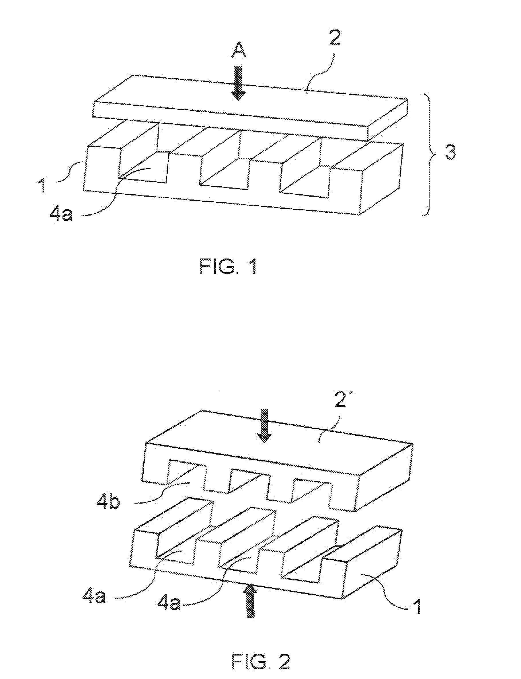
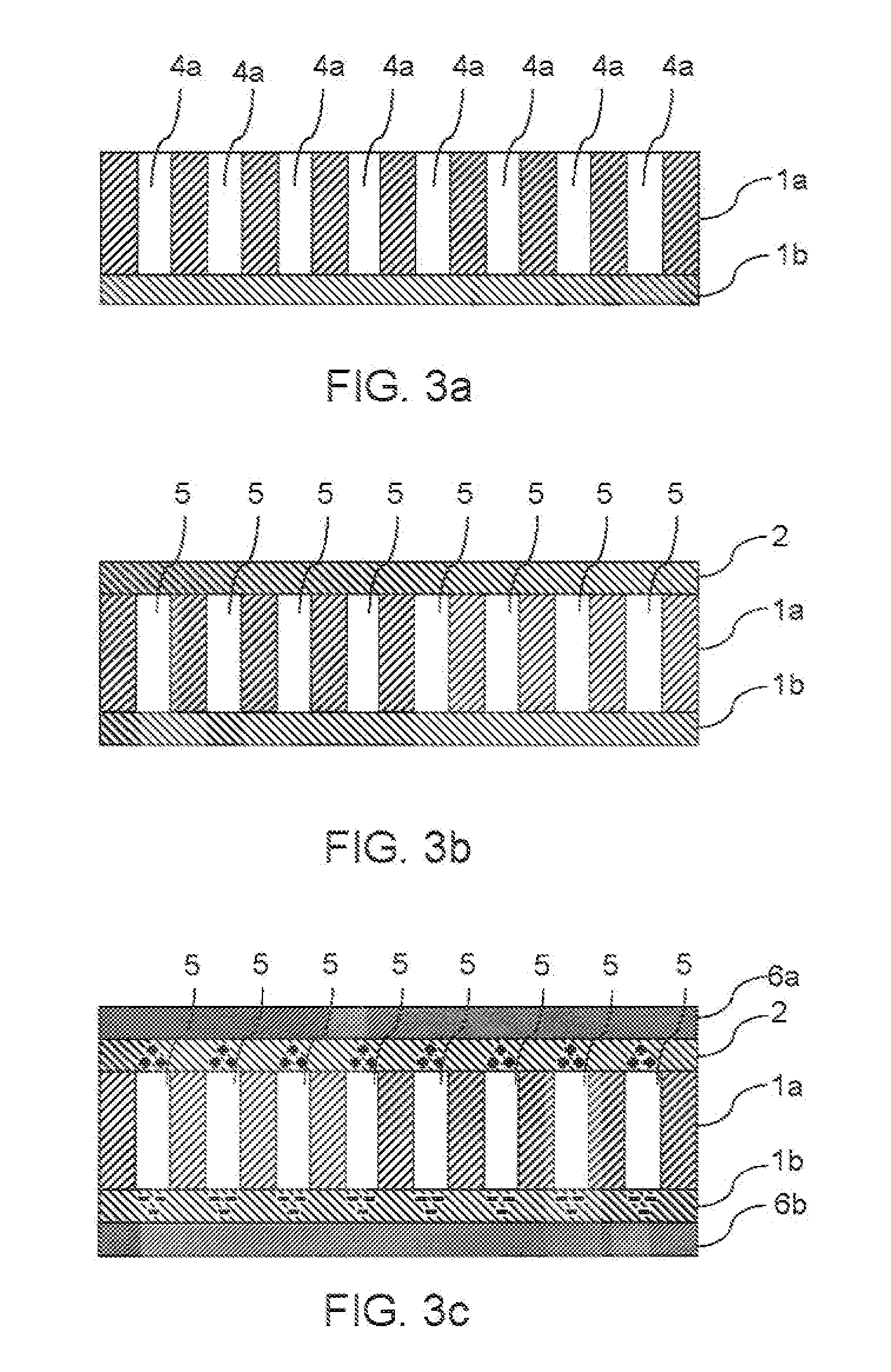
[0022]According to the invention, a method for producing a two- or multi-layer ferroelectret with voids, with the exception of a three-layer ferroelectret with a perforated middle layer made of PTFE between two FEP layers, involving the following steps:[0023]A) introducing one or more clearances into at least one surface side of a polymer film element by means of a method of removal, ,[0024]B) applying a first covering to the surface side of the polymer film element having clearances formed in step A), and[0025]C) joining the polymer film element and the first covering to form a two- or multi-layer ferroelectret, the clearances being closed while voids are formed.

[00...


PUM


Abstract

The present invention relates to a method for producing two- or multi-layer ferroelectrets with defined voids, with the exception of three-layer ferroelectrets with a perforated middle layer made of PTFE between two FEP layers, involving, introducing one or more clearances into at least one surface side of a polymer film element by means of a method of removal, applying a first covering to the surface side of the polymer film element comprising clearances formed in step A), and joining the polymer film element and the covering to form a polymer film composite, the clearances being closed while voids are formed, and to a two- or multi-layer ferroelectret, with the exception of three-layer ferroelectrets with a perforated middle layer made of PTFE between two FFP layers, in particular produced by this method. The invention also relates to a piezoelectric element containing a ferroelectret multi-layer composite according to the invention.

Description

FIELD OF THE INVENTION[0001]The present invention relates to a method for producing two- or multi-layer ferroelectrets, with the exception of three-layer ferroelectrets with a perforated middle layer made of PTFE between two HP layers, with voids and to two- and multi-layer ferroelectrets produced by this method.BACKGROUND OF THE INVENTION[0002]Piezoelectric materials are capable of converting a mechanical pressure linearly into an electrical voltage signal. Conversely, an electric field applied to the piezoelectric material can be transformed into a change in the geometry of the transducer. Piezoelectric materials are already integrated as active components in many applications. These include, for example, structured pressure sensors for keyboards or touchpads, acceleration sensors, microphones, loudspeakers, ultrasonic transducers for applications in medical engineering, marine technology or materials testing. In WO 2006 / 053528 A1, for example, a description is given of an electro...

Claims


Application Information

Patent Timeline
IPC IPC(8): H01L41/04H01L41/113H01L41/26H01L41/277H01L41/45
CPCH01G4/20H01L41/083H01L41/193Y10T29/42H01L41/45H04R17/005H01L41/277H10N30/50H10N30/057H10N30/857H10N30/098
Inventor JENNINGER, WERNERWAGNER, JOACHIMBENECKE, CARSTEN
Owner BAYER MATERIALSCIENCE AG
Why Eureka
Try Eureka