Virtual microscope system

Active Publication Date: 2011-05-12
EVIDENT CORP
View PDF4 Cites 27 Cited by
  • Summary
  • Abstract
  • Description
  • Claims
  • Application Information

AI Technical Summary

Benefits of technology

[0059]The virtual microscope system according to the present invention can create statistical data of spectra

Problems solved by technology

Thus the user needs to measure the spectrum of each main element of the sample previously with a spectrometer while moving the measuring position,

Method used


Image

  • Virtual microscope system
  • Virtual microscope system
  • Virtual microscope system

Examples


first embodiment

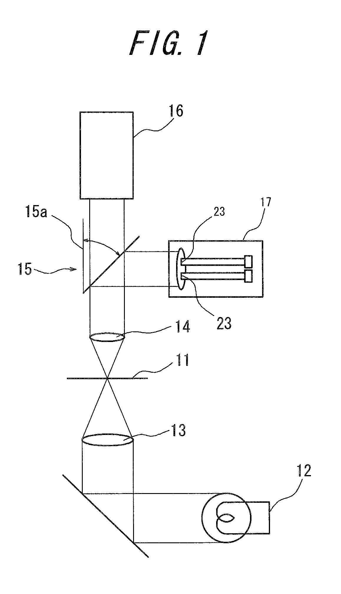
[0079]FIGS. 1 and 2 are diagrams for illustrating the principles of a virtual microscope system in accordance with a first embodiment of the present invention. In the virtual microscope system in accordance with the present embodiment, a stained sample (hereinafter referred to as an “object sample”) 11 that is placed on a stage of a microscope apparatus is illuminated by a light source 12 through an illumination optical system 13, and the light transmitted therethrough is incident on an optical path setting unit 15 through an observation optical system 14 comprising a microscope objective lens. The optical path setting unit 15 is, for example, constituted by an optical path switching mirror 15a. The optical path switching mirror 15a is constituted, for example, by a reflective mirror that is evacuatable relative to the optical path of the incident light. The optical path of the incident light from the observation optical system 14 is directed to an image obtaining unit 16 by evacuat...

second embodiment

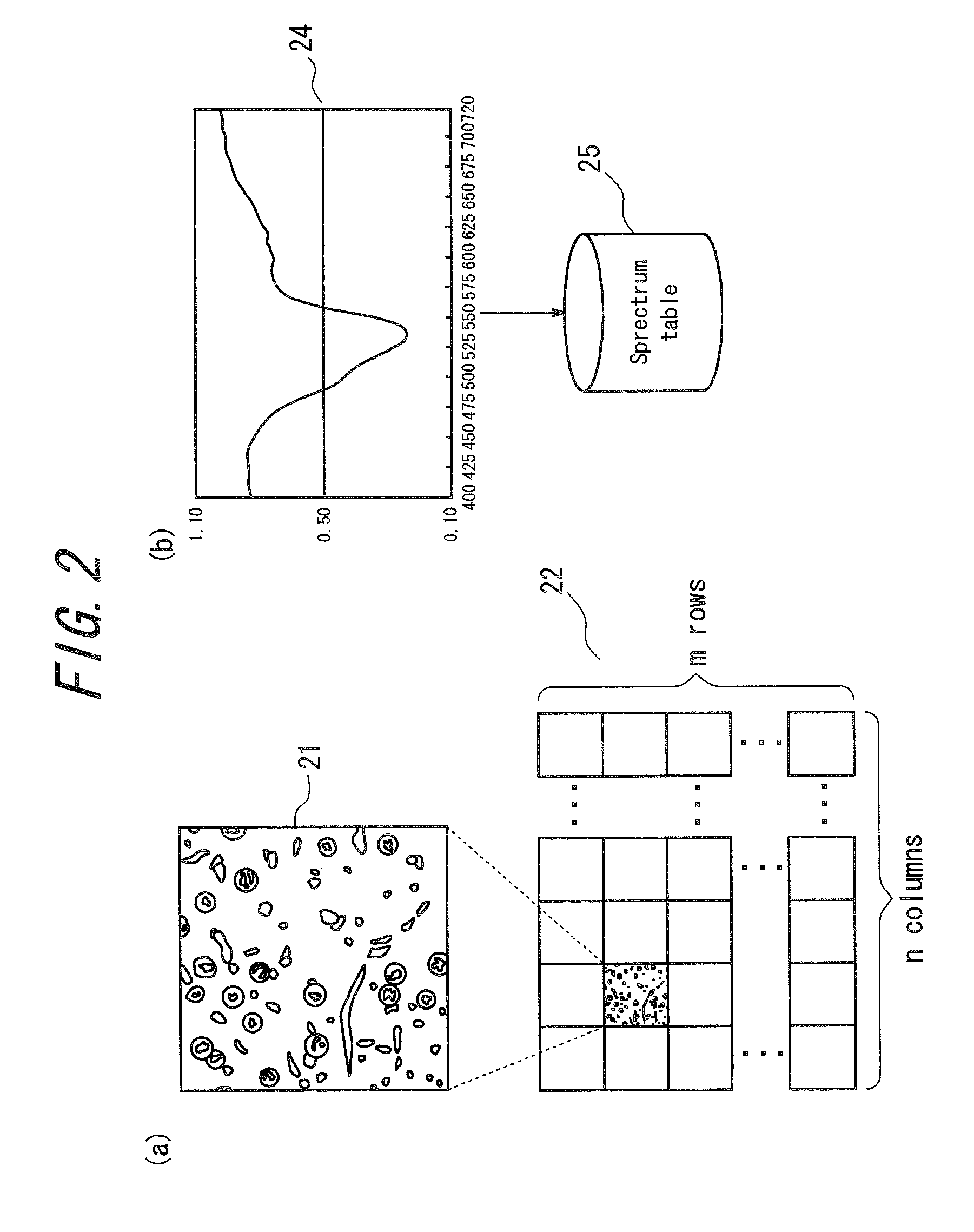
[0122]FIGS. 12(a) and 12(b) are diagrams for illustrating the principles of a virtual microscope system in accordance with a second embodiment of the present invention. In the virtual microscope system in accordance with the present embodiment, in addition to the operation principles of the first embodiment described by FIGS. 2(a) and 2(b), when the spectrum 24 obtained from the object sample image is registered in the spectrum table 25, the pixel value of the pixel and the position information of the portion 23 where the spectrum 24 is measured are obtained from the object sample image 21 and are stored as a data set 26 in the spectrum table 25, thereby creating a spectrum table containing a pixel value almost simultaneously with creation of a virtual slide. Other than that are the same as the principles shown in FIGS. 2(a) and 2(b).

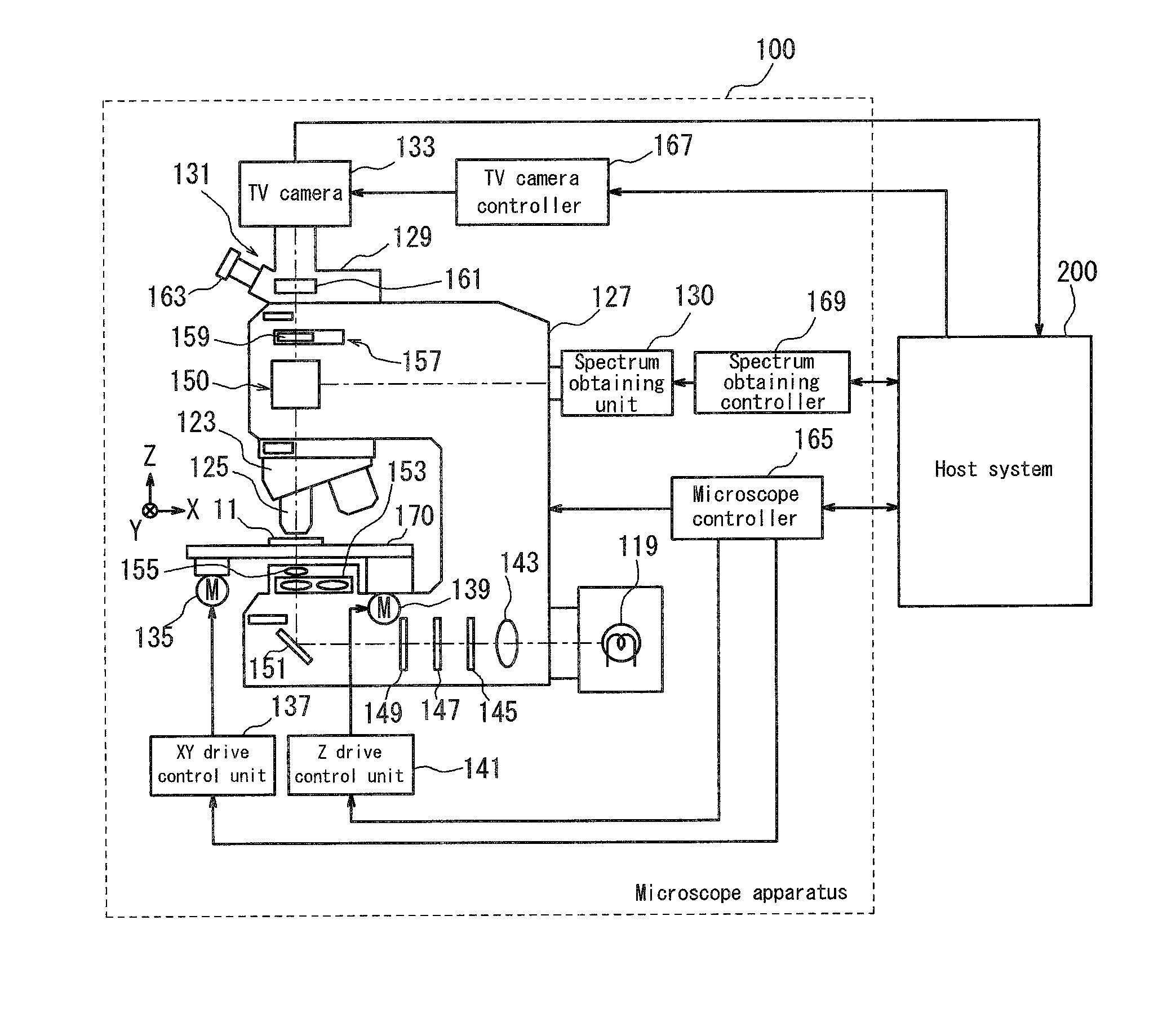
[0123]FIG. 13 is a functional block diagram showing a configuration of the virtual microscope system in accordance with the present embodiment based on...


PUM


Abstract

A virtual microscope system capable of obtaining a stained sample image and a statistical data of spectra in a short period of time is provided, the virtual microscope system includes an image obtaining unit for obtaining a stained sample image, a spectrum obtaining unit for obtaining a spectrum of the stained sample image, an optical path setting unit for setting an optical path of a light flux passed through the stained sample with respect to the image obtaining unit and the spectrum obtaining unit and a control unit for controlling to repeat obtaining the stained sample image by the image obtaining unit and obtaining the spectrum of the stained sample image by the spectrum obtaining unit in the observation field of the stained sample to create a virtual slide and a spectrum table of the stained sample.

Description

CROSS-REFERENCE TO RELATED APPLICATION[0001]The present application claims priority from Japanese Application No. 2009-256312 filed on Nov. 9, 2009, the content of which is incorporated herein by reference.FIELD OF THE INVENTION[0002]The present invention relates to virtual microscope systems for estimating spectra of a stained sample image obtained by capturing a stained sample.BACKGROUND OF THE INVENTION[0003]The spectral transmittance spectrum is one of physical quantities representing a physical property specific to a subject of imaging. The spectral transmittance is a physical quantity representing a ratio of transmitted light to incident light at each wavelength and, unlike the color information such as an RGB value that depends on the change of illumination light, is the information specific to an object, whose values do not change depending on extrinsic influences. Thus the spectral transmittance is used in various fields as the information to reproduce the color of the subj...

Claims


Application Information

Patent Timeline
IPC IPC(8): H04N7/18
CPCG01J3/02G01J3/0248G01J3/027G02B21/365G01J3/32G01J3/42G01J3/08
Inventor OTSUKA, TAKESHI
Owner EVIDENT CORP
Why Eureka
Try Eureka