Optical Positioning Apparatus And Positioning Method Thereof

a positioning apparatus and optical technology, applied in the field of positioning apparatus, can solve the problems of poor positioning accuracy, low optical efficiency, complicated layout and use of optical mouse, etc., and achieve the effect of convenient layout and us

Inactive Publication Date: 2011-05-12
CHENG UEI PRECISION IND CO LTD
View PDF6 Cites 3 Cited by
  • Summary
  • Abstract
  • Description
  • Claims
  • Application Information

AI Technical Summary

Benefits of technology

[0008]As described above, the optical positioning apparatus and method of the present invention utilize the first and the second optical sensors to sense the calibrating device and the object, then utilize the processor to execute the calib

Problems solved by technology

However, the optical mouse has disadvantages of complicated layout and use.
Moreover, when the LED becomes dimmer, the optical mouse

Method used


Image

  • Optical Positioning Apparatus And Positioning Method Thereof
  • Optical Positioning Apparatus And Positioning Method Thereof
  • Optical Positioning Apparatus And Positioning Method Thereof

Examples


Embodiment Construction

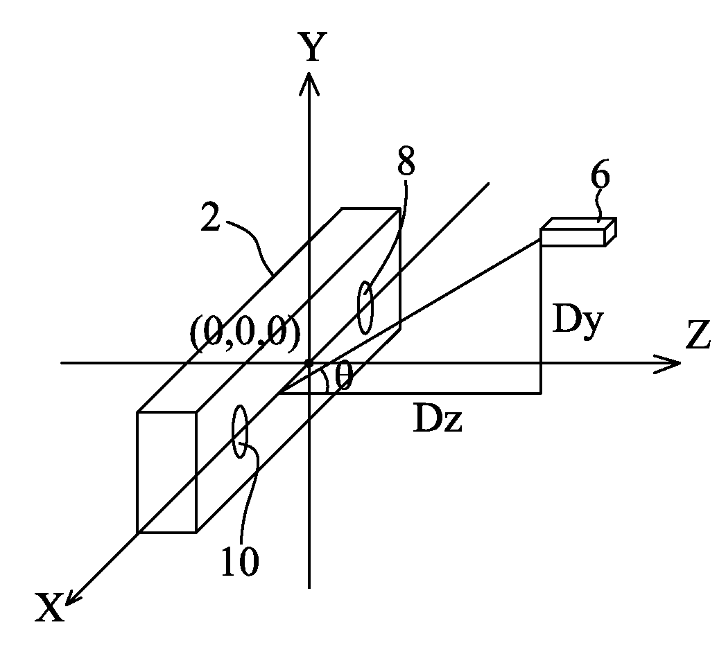
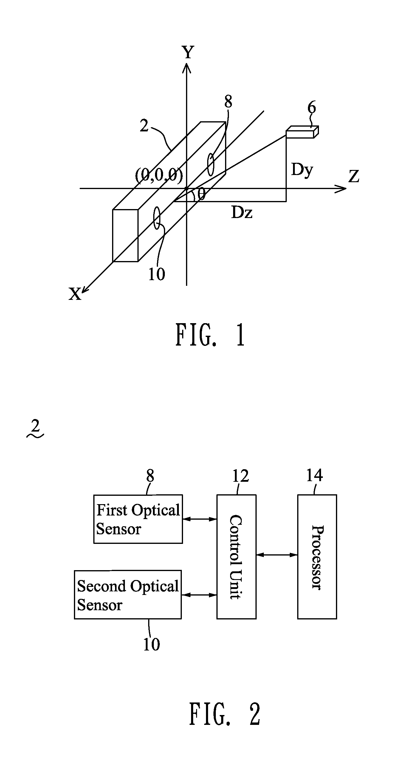
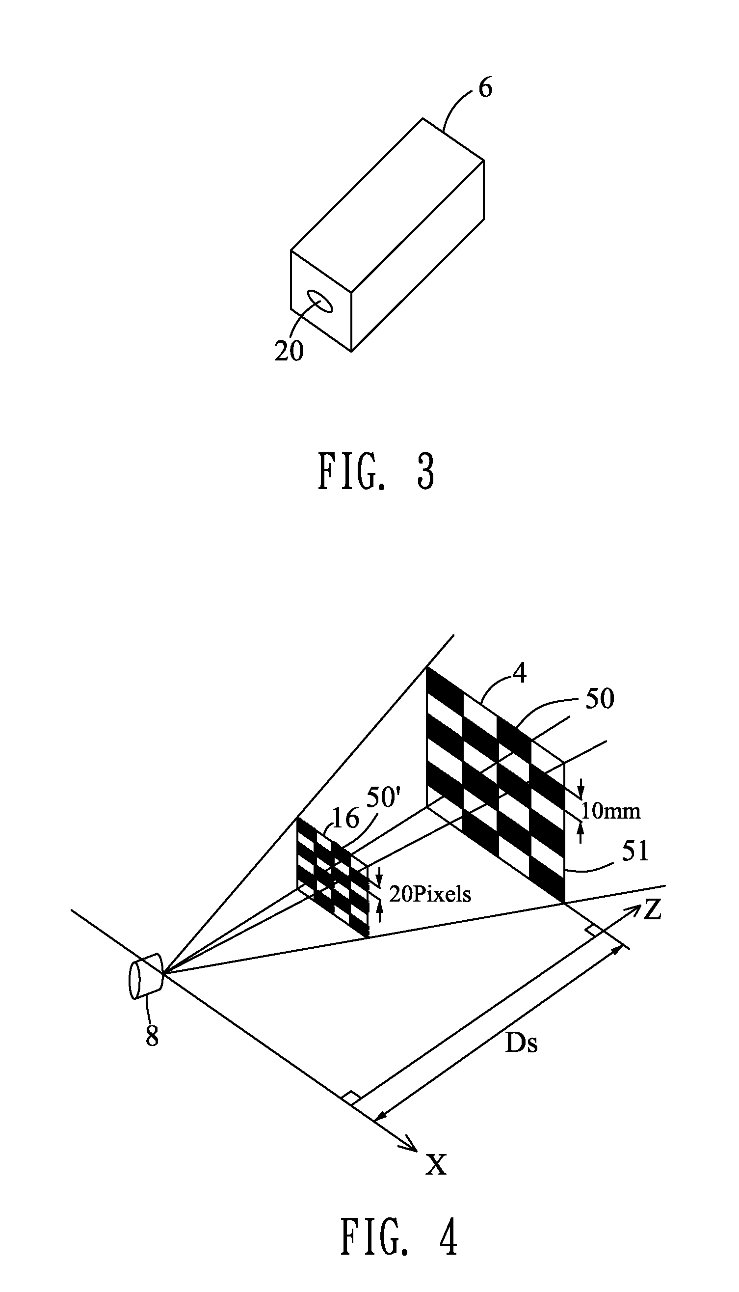
[0017]With reference to FIG. 1, FIG. 2 and FIG. 4, an optical positioning apparatus according to a first embodiment of the present invention is adapted for determining a position of an object 6 in a three-dimensional coordinate system which has a first axis X, a second axis Z and a third axis Y to obtain a coordinate (Dx, Dz, Dy), where Dx is the coordinate of the object 6 in the first axis X, Dz is the coordinate of the object 6 in the second axis Z, and Dy is the coordinate of the object 6 in the third axis Y. The optical positioning apparatus includes a host device 2 and a calibrating device 4.

[0018]Referring to FIG. 2 again, the host device 2 includes a first optical sensor 8, a second optical sensor 10, a control unit 12 and a processor 14. The first optical sensor 8 and the second optical sensor 10 are respectively connected with the control unit 12, and the control unit 12 is further connected with the processor 14. The control unit 12 receives image signals of the calibratin...


PUM


Abstract

An optical positioning apparatus and method are adapted for determining a position of an object in a three-dimensional coordinate system which has a first axis, a second axis and a third axis perpendicular to one another. The optical positioning apparatus includes a host device which has a first optical sensor and a second optical sensor located along the first axis with a first distance therebetween, and a processor connected with the optical sensors, and a calibrating device placed in the sensitivity range of the optical sensors with a second distance between an origin of the second axis and a coordinate of the calibrating device projected in the second axis. The optical sensors sense the calibrating device to make the processor execute a calibrating procedure, and then sense the object to make the processor execute a positioning procedure for determining the position of the object in the three-dimensional coordinate system.

Description

BACKGROUND OF THE INVENTION[0001]1. Field of the Invention[0002]The present invention generally relates to a positioning apparatus, and more particularly to an optical positioning apparatus and a positioning method thereof.[0003]2. The Related Art[0004]Optical positioning apparatuses are well known. They are utilized in a variety of applications, including common automatic toilet flushers, video games, and sophisticated laser guided munitions etc. It is an example that optical mice control the video games as follows. The optical mouse relies on a light emitting diode (LED) illuminating a surface at grazing incidence, a two-dimensional CMOS detector which captures the resultant images, software that correlates successive images to determine the position, and speed sensors determining the speed the mouse has been moved.[0005]However, the optical mouse has disadvantages of complicated layout and use. Moreover, when the LED becomes dimmer, the optical mouse suffers from a low optical ef...

Claims


Application Information

Patent Timeline
IPC IPC(8): G06K9/00G01B11/14G01J1/10G01B11/00
CPCG01B11/002G01S3/7803G01S3/784G06T2207/10012G06F3/0325G06T7/002G01S5/16G06T7/85G01B11/00G01C11/06G01C11/30G01P3/38G01P15/18G06T7/70G06T7/97
Inventor CHEN, YU-HSIANGCHENG, AN-SHUN
Owner CHENG UEI PRECISION IND CO LTD
Why Eureka
Try Eureka