Wound dressing with micropump

a micro-pump and wound dressing technology, applied in the field of wound dressings with micro-pumps, can solve the problems of less able to close naturally, less able to successfully close, difficult to close, etc., and achieve the effects of less complicated, convenient ambulation, and greater patient comfor

Inactive Publication Date: 2011-05-12
3M INNOVATIVE PROPERTIES CO
View PDF73 Cites 217 Cited by
  • Summary
  • Abstract
  • Description
  • Claims
  • Application Information

AI Technical Summary

Benefits of technology

[0015]Unlike other types of wound vacuum systems, the configuration of the system disclosed eliminates the use of “fluid traps” which can become filled and thus contaminate the reusable motorized micropumps associated therewith. Such systems also must be shut down in order to drain the trap. The positive pressure wound fluid accum...

Problems solved by technology

Unfortunately, closure is difficult with large wounds or wounds that have become infected.
Without sufficient blood flow, the epithelial and subcutaneous tissues surrounding the wound not only receive diminished oxygen and nutrients, but, are also less able to successfully fight microbial infection and, thus, are less able to close naturally.
Such wounds have presented difficulties to medical personnel for many years.
For example, skin ulcers are a common problem among many diabetics, and are often brought on by poor blood circulation and nerve damage associated with diabetes and/or vascular disease.
Furthermore, many wounds can become stalled in a “chronic condition” in which further healing does not occur and, in fact, wound may actually increase in size and depth.
Although transparent dressings can “breathe”, they often do not have sufficient moisture vapor transmission rates (MVTR) to allow evaporation of excess wound flui...

Method used


Image

  • Wound dressing with micropump
  • Wound dressing with micropump
  • Wound dressing with micropump

Examples


example 1

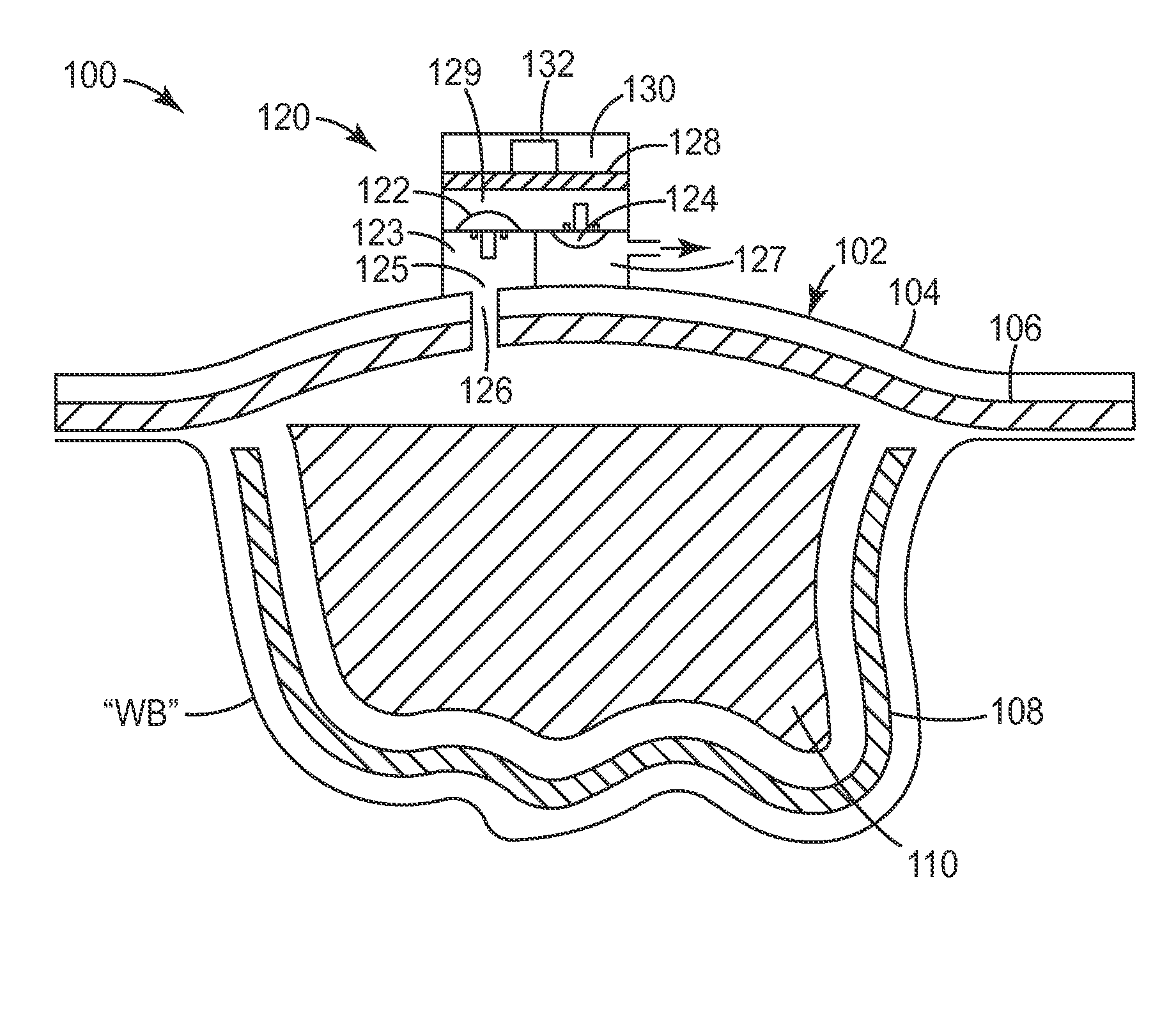
[0178]FIG. 15 is a cross-sectional schematic diagram of this example. A Tegaderm™ (3M Company, Maplewood Minn.) wound dressing 102 is used to seal a wound cavity defined by the wound bed “WB” and the wound dressing. The wound cavity is filled with a wound packing 110. A diaphragm micropump is fixed to the exterior surface of the wound dressing backing The micropump extracts fluid (air and wound exudate) and moves this fluid through the exudate collection line to a to a flexible collection pouch 150. Although shown with a single micropump multiple micropumps may be used over a single wound site. The collection pouch is designed very similar to an ostomy bag and can be worn in a similar manner. The collection pouch may be sealed or vented. In a preferred embodiment it is not vented. If vented, it may include a vent filter to reduce order that may be generated from the wound fluid. A valve is placed in the exudate collection line 140 which may be used to collect samples of wound fluid ...

example 2

[0185]The wound dressing evacuation system of Example 1 is employed except that the micropump is supplied separately in a kit with the wound dressing. The kit comprises the micropump, wound dressing, wound packing material with an integral (bonded) wound contact layer, evacuation line and wound fluid exudate collection pouch. As in Example 1, the wound packing / contact layer is cut to size and placed in the wound. The dressing is placed over the entire wound making certain to seal well to the surrounding tissue and forming a hermetic seal. The micropump comprises a pressure sensitive adhesive on its base. The micropump is positioned over the preformed orifice in the dressing (126). In this embodiment the micropump may be reusable (but preferably only on a single patient) and applied to several dressings in succession as needed.

example 3

[0186]The wound dressing evacuation system of Example 2 is employed except that the dressing is not supplied with an orifice. Instead the orifice is created by the clinician using a supplied punch which may be similar in operation to a hand held paper hole punch. The orifice may be placed anywhere on the dressing the clinician prefers such as in the center or along the periphery. Multiple orifices and multiple micropumps are employed.


PUM


Abstract

A composite wound dressing apparatus promotes healing of a wound via the use of a micropump system. The micropump system includes a micropump that applies a subatmospheric pressure to the wound to effectively draw wound fluid or exudate away from the wound bed, or deliver fluids to the wound bed, without the need for a cumbersome external pressure (e.g. vacuum) source. Hence, the wound dressing and micropump system is portable which allows the patient mobility that is unavailable when an external vacuum source is used.

Description

FIELD OF THE INVENTION[0001]The present disclosure relates to an apparatus for treating an open wound, and, more specifically, relates to a wound dressing with a micropump adapted for both introducing fluids into and evacuating fluids from a wound to facilitate the wound healing process.BACKGROUND[0002]Wound closure involves the migration of epithelial and subcutaneous tissue adjacent the wound towards the center of the wound until the wound closes. Unfortunately, closure is difficult with large wounds or wounds that have become infected. In such wounds, a zone of stasis (i.e. an area in which localized swelling of tissue restricts the flow of blood to the tissues) forms near the surface of the wound. Without sufficient blood flow, the epithelial and subcutaneous tissues surrounding the wound not only receive diminished oxygen and nutrients, but, are also less able to successfully fight microbial infection and, thus, are less able to close naturally. Such wounds have presented diffi...

Claims


Application Information

Patent Timeline
IPC IPC(8): A61M1/00
CPCA61F13/02A61M1/009A61M27/00A61M1/0088A61F13/0226A61F13/0216A61M1/962A61M1/82A61M1/984A61F2013/0054A61F13/00068A61F2013/00536A61M1/78A61M1/74A61M1/80
Inventor BHARTI, VIVEKSCHOLZ, MATTHEW T.
Owner 3M INNOVATIVE PROPERTIES CO
Why Eureka
Try Eureka