Graphite Tape Supply and Backing Paper Take-Up Apparatus

Active Publication Date: 2011-05-19
THE BOEING CO
View PDF99 Cites 11 Cited by
  • Summary
  • Abstract
  • Description
  • Claims
  • Application Information

AI Technical Summary

Benefits of technology

In accordance with the present disclosure, a graphite composite tape supply and backing paper take-up apparatus is provided for use in conjunction with a composite tape laminating machine that enable

Problems solved by technology

The narrow tapes cannot be “single-wound,” i.e., in the manner of a movie film, onto reels of a corresponding width because the diameter of the reels would have to be increased substantially to accommodate a useful amount of tape thereon, and hence, would have an unacceptably high inertia.
Because the existing solutions do not actively control the dancer position, they have great difficulty controlling large supply reels with varying inertias.
Thus, the existin

Method used


Image

  • Graphite Tape Supply and Backing Paper Take-Up Apparatus
  • Graphite Tape Supply and Backing Paper Take-Up Apparatus
  • Graphite Tape Supply and Backing Paper Take-Up Apparatus

Examples


Embodiment Construction

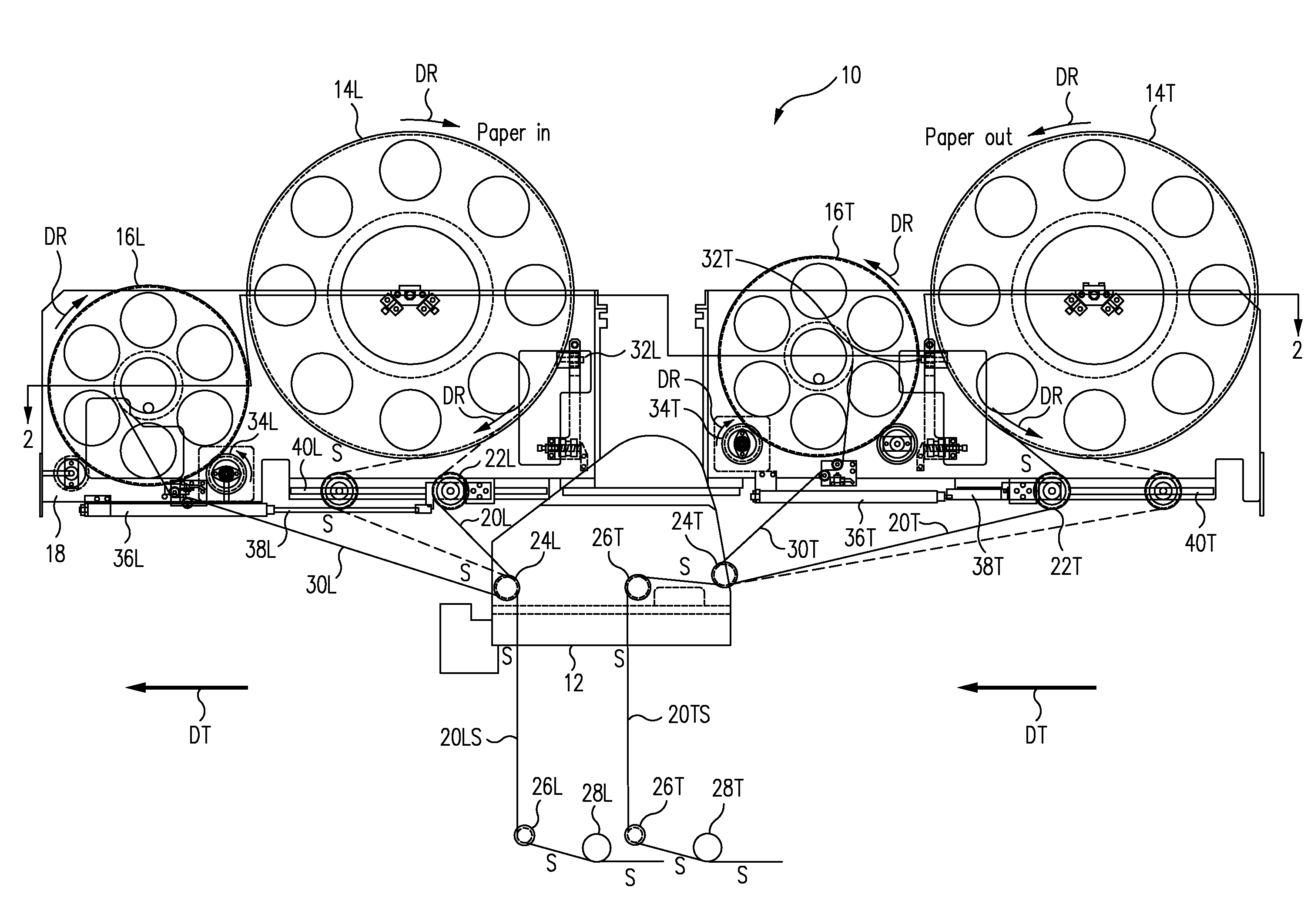
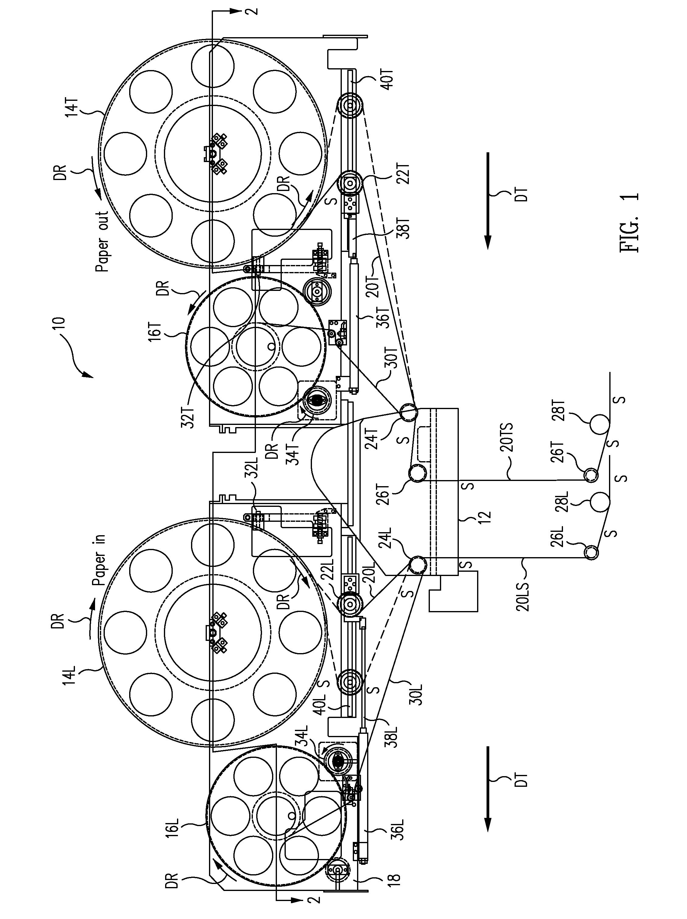
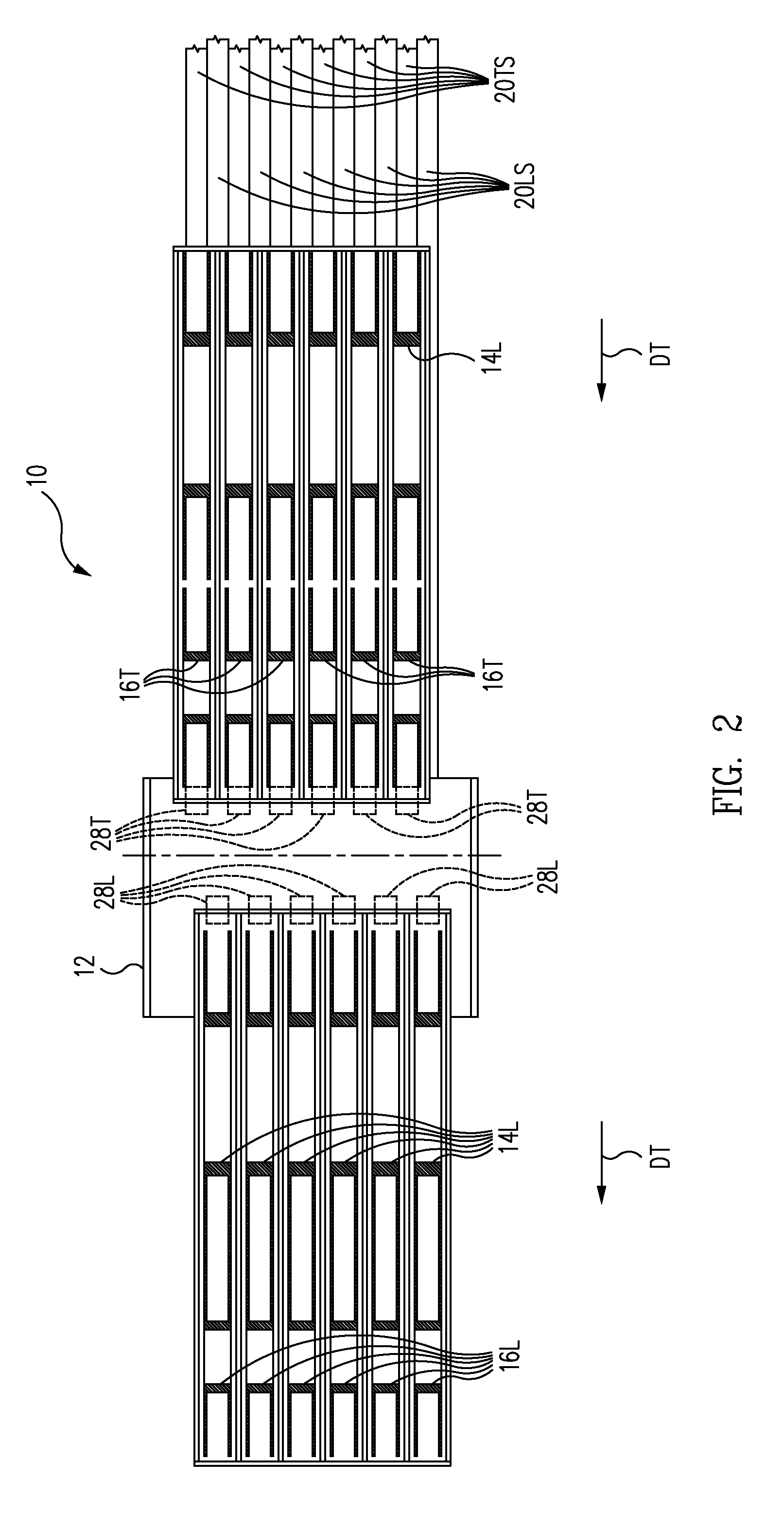
An exemplary embodiment of a graphite tape supply and backing paper take-up apparatus 10 in accordance with the present disclosure is illustrated in the partial elevation view of FIG. 1. FIG. 2 is a cross-sectional view of the exemplary apparatus 10, as seen along the lines of the section 2-2 taken in FIG. 1. FIG. 3 is a functional block diagram of an exemplary tape supply and backing paper take-up portion of the apparatus of FIGS. 1 and 2.

As may be seen by reference to FIGS. 1-3, the exemplary apparatus 10 comprises a pair of graphite tape supply reels 14L and 14T and an associated pair of backing paper take-up reels 16L and 16T, which may be mounted on a support frame 18 of the laminating machine for independent rotation in the direction of the arrows DR respectively associated with each reel 14L, 14T, 16L and 16T during the tape laminating process.

During the laminating process, the laminating machine (not illustrated), including the tape laminating head 12 thereof, may move in th...


PUM

PropertyMeasurementUnit
Widthaaaaaaaaaa
Tensionaaaaaaaaaa

Abstract

An apparatus for supplying one or more strands of a relatively wide tape to a high-speed graphite tape laminating machine may include a tape supply reel and a backing paper take-up reel rotatably mounted on the machine, a dancer roller mounted on the machine for lateral movement thereon, and a mechanism for actively controlling the rotation of the tape supply and backing paper take-up reels and the lateral movement of the dancer roller relative to the support frame such that the respective tensions in the tapes are maintained substantially constant during both an on-the-fly tape add operation and an on-the-fly tape cut operation of the laminating machine.

Description

BACKGROUNDThis disclosure generally relates to tools used in the manufacture of composite structures, and in particular, to a graphite composite tape supply and backing paper take-up apparatus for use in conjunction with a high speed, composite tape laminating machine that enables the use of larger tape supply reels and substantially wider tapes, thereby achieving higher lamination rates and lower material costs in the lamination process.The demand for large, complex composite parts, such as are used, for example, in composite air frames, is growing rapidly. These parts are typically produced by laying parallel strips of a composite tape, e.g., unidirectional graphite fiber tape impregnated with an uncured resin (a “prepreg”), immediately adjacent to each other on a forming tool, then curing the resin. The growing demand is typically being satisfied by suppliers in one of two ways: 1) by purchasing multiple, current-technology laminating machines, or 2) by developing machines that c...

Claims


Application Information

Patent Timeline
IPC IPC(8): B29C70/56B65H77/00
CPCB29C70/386B65H23/048B65H23/063Y10T156/16B65H37/002Y10T156/17Y10T156/1052B65H35/0013B65H59/38B65H59/00B65H23/00
Inventor HAGMAN, THOMAS J.BUNKER, MARK S.
Owner THE BOEING CO
Why Eureka
Try Eureka