Information Device
a technology of information device and smoothing capacitor, which is applied in emergency power supply arrangements, relays, instruments, etc., can solve the problems of internal circuit failure, internal circuit failure, and insufficient discharge of residual charge in smoothing capacitors, etc., and achieve the effect of lessening work disruption
- Summary
- Abstract
- Description
- Claims
- Application Information
AI Technical Summary
Benefits of technology
Problems solved by technology
Method used
Image

Examples
embodiment 1
A. Embodiment 1
A1. System Configuration
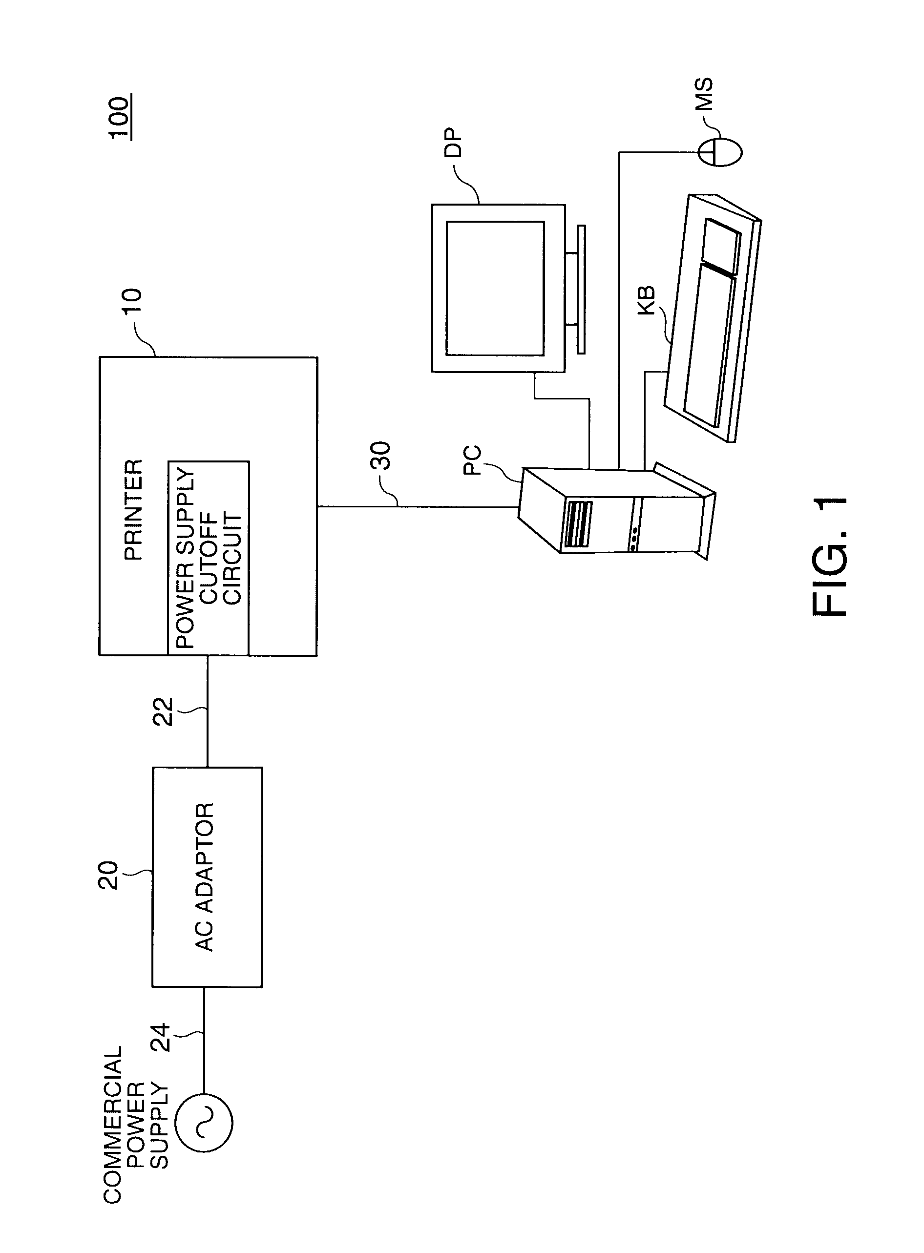
[0047]FIG. 1 schematically describes the configuration of a computer system 100 that includes an information device as a first embodiment of the invention. This computer system 100 includes a personal computer PC and a printer 10 as an example of an information device according to the invention.
[0048]An AC adaptor 20 is connected to the printer 10 through a power cable 22. The AC adaptor 20 is connected to a commercial power supply through power cable 24. The AC adaptor 20 converts the AC power supplied from the commercial power source to DC power, and supplies DC power to the printer 10. The AC adaptor 20 is a power supply device.
[0049]A personal computer PC is connected to the printer 10 through a printer cable 30. A keyboard KB, mouse MS, and display DP are connected to the personal computer PC. The printer 10 prints when a print job is received from the personal computer PC.
[0050]To suppress power consumption, the printer 10 according to th...
embodiment 2
B. Embodiment 2
[0084]A printer according to the second embodiment of the invention has a power supply mode and a power cutoff mode as operating modes similarly to the printer 10 according to the first embodiment of the invention. However, the configuration of the power supply cutoff circuit in the printer according to the second embodiment of the invention differs from that of the printer 10 according to the first embodiment of the invention. The configuration and operation of the power supply cutoff circuit in a printer according to the second embodiment of the invention is described next.
B1. Power Supply Cutoff Circuit Configuration
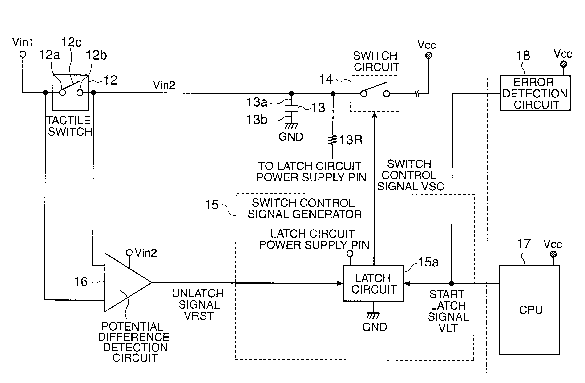
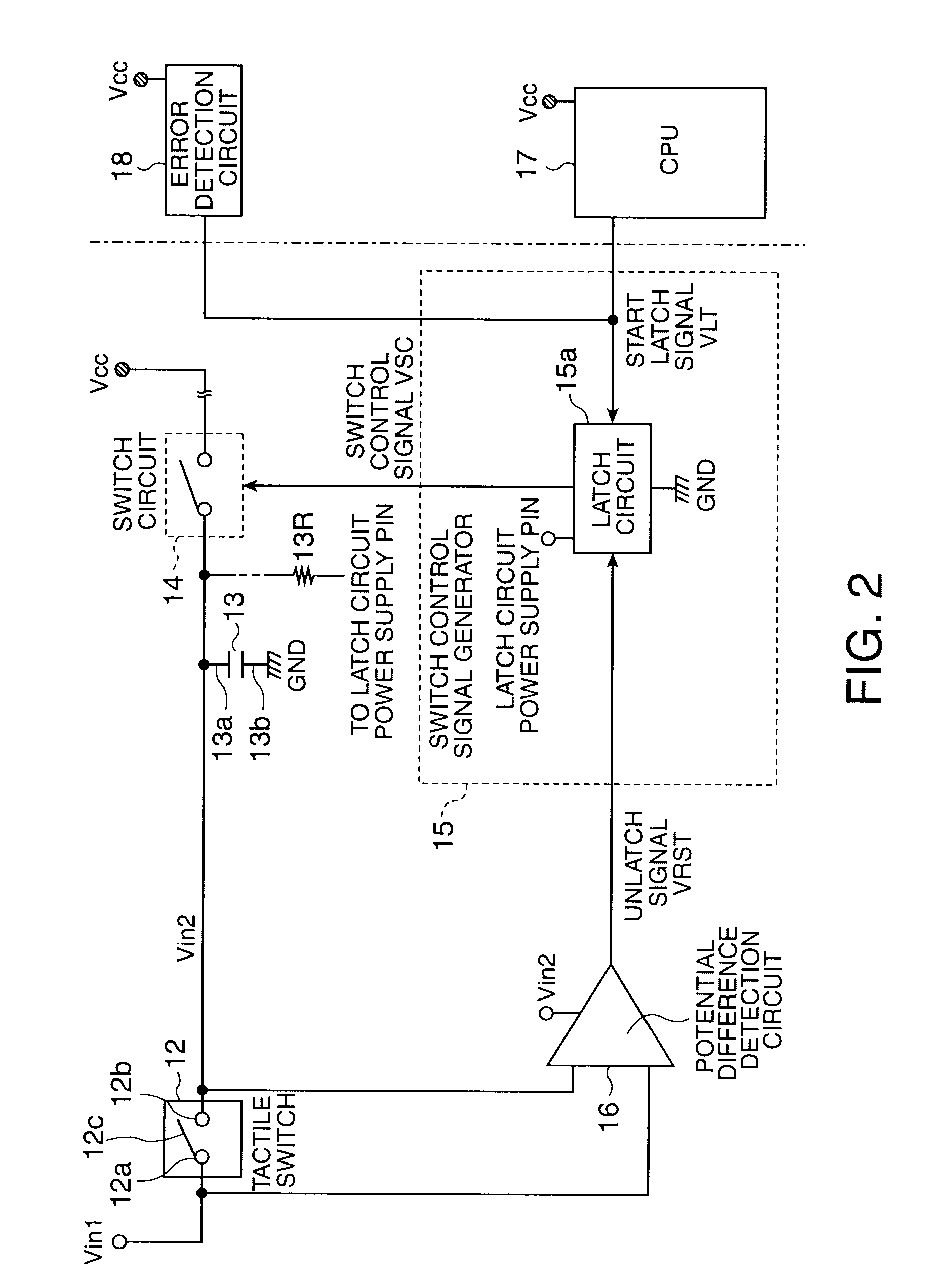
[0085]FIG. 6 schematically describes the configuration of the power supply cutoff circuit in a printer according to the second embodiment of the invention. As will be known by comparing FIG. 6 and FIG. 2, the power supply cutoff circuit of the printer according to the second embodiment of the invention has a switch control signal generator 15A instead o...
embodiment 3
C. Embodiment 3
[0092]A printer according to the third embodiment of the invention has a power supply mode and a power cutoff mode as operating modes similarly to the printer 10 according to the second embodiment of the invention. However, the configuration of the power supply cutoff circuit in the printer according to this third embodiment differs from that of the printer 10 according to the second embodiment of the invention. The configuration and operation of the power supply cutoff circuit in a printer according to the third embodiment of the invention is described next.
C1. Power Supply Cutoff Circuit Configuration
[0093]FIG. 8 schematically describes the configuration of the power supply cutoff circuit in a printer according to the third embodiment of the invention. As will be known by comparing FIG. 8 and FIG. 6, the power supply cutoff circuit of the printer according to the third embodiment of the invention has a switch control signal generator 15B instead of the switch contro...
PUM
 Abstract
Description
Claims
Application Information
 - R&D
- Intellectual Property
- Life Sciences
- Materials
- Tech Scout
- Unparalleled Data Quality
- Higher Quality Content
- 60% Fewer Hallucinations
Browse by: Latest US Patents, China's latest patents, Technical Efficacy Thesaurus, Application Domain, Technology Topic, Popular Technical Reports.
© 2025 PatSnap. All rights reserved.Legal|Privacy policy|Modern Slavery Act Transparency Statement|Sitemap|About US| Contact US: help@patsnap.com