Pm motor drive power supply apparatus

Inactive Publication Date: 2011-05-19
MERSTECH
View PDF1 Cites 12 Cited by
  • Summary
  • Abstract
  • Description
  • Claims
  • Application Information

AI Technical Summary

Benefits of technology

[0023]When direct-current pulse voltage higher than power voltage is generated by utilizing pulse voltage generating means with an MERS and is supplied to a synchronous motor via polarity switching means, necessary voltage and current in a high speed range can be obtained. Accordingly, the synchronous motor provides high speed and high power (i.e., high torque). In the synchronous motor drive power supply apparatus according to the present invention, the pulse voltage generating means with an MERS is applied for a synchronous motor drive power supply apparatus.

Problems solved by technology

Hence, there has been a problem that a capacitor of the voltage source becomes large in electrostatic capacitance and physical size.
However, this method is undeniable that the efficiency thereof drops.
Further, a high-voltage layered battery used for an electric automobile has a problem of performance deterioration and a risk of electric shock and the like.

Method used


Image

  • Pm motor drive power supply apparatus
  • Pm motor drive power supply apparatus
  • Pm motor drive power supply apparatus

Examples


embodiments

First Embodiment

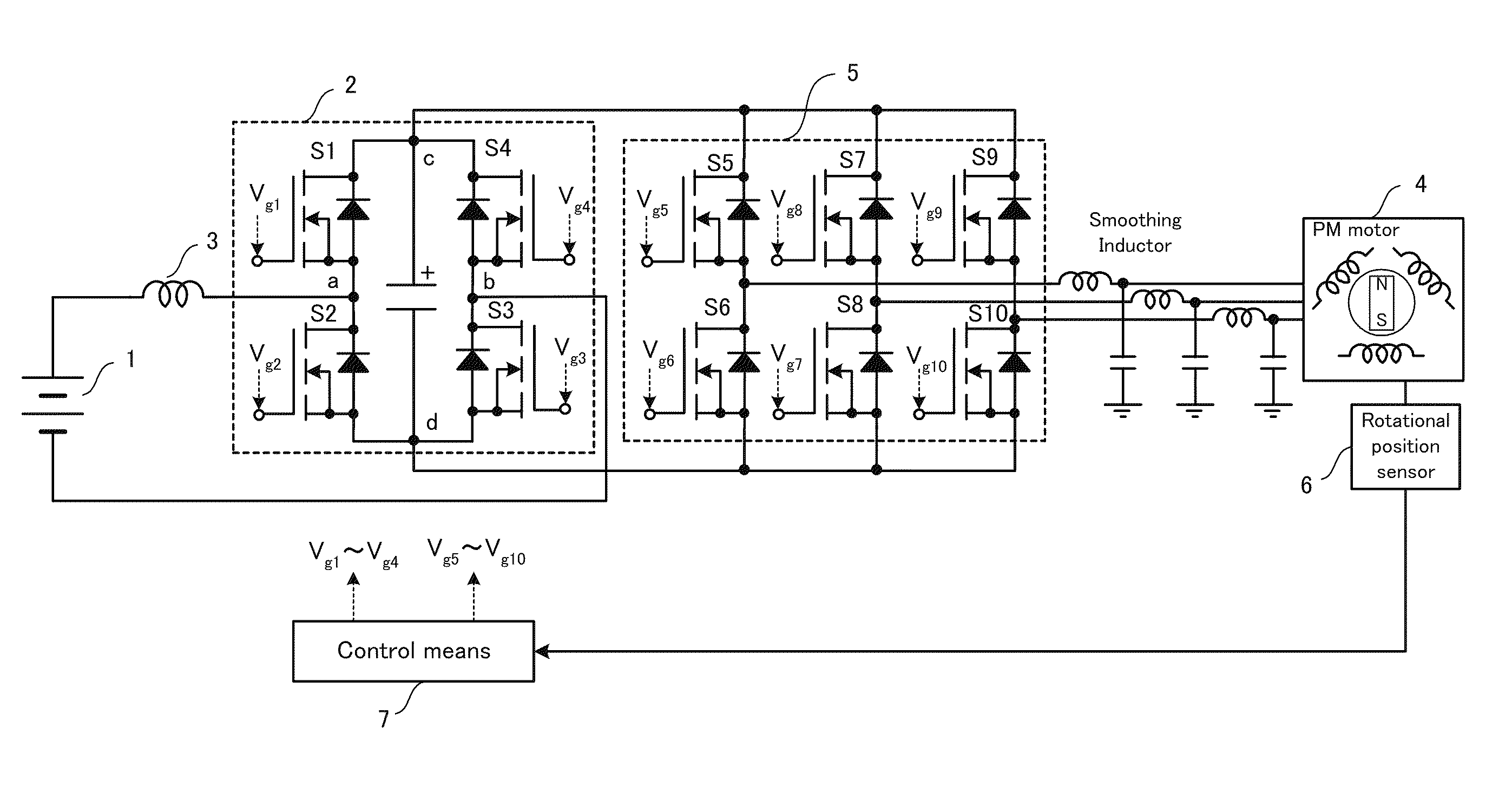
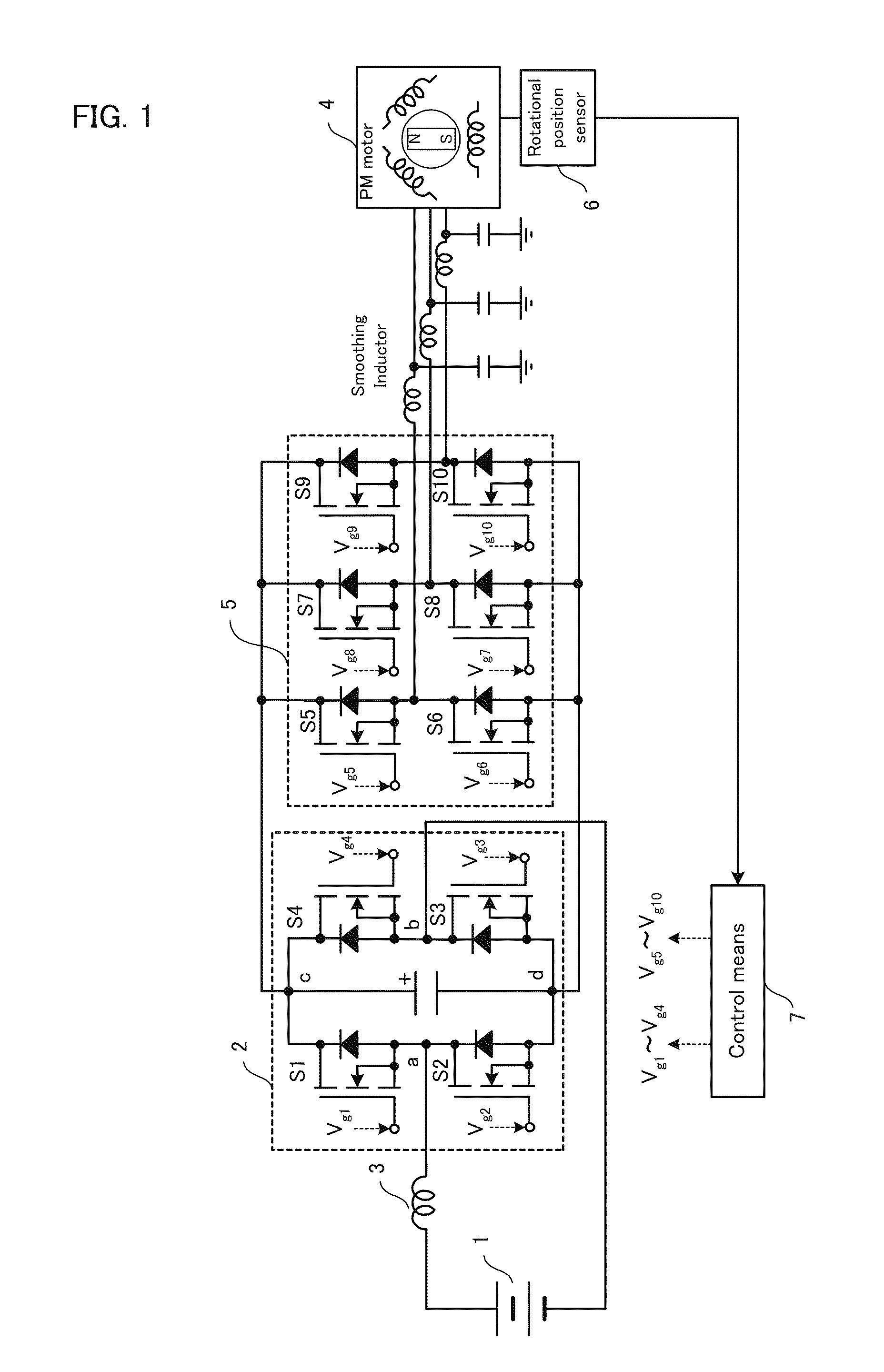
[0037]FIG. 1 is a circuit block diagram (hereinafter, called a circuit diagram) showing a first embodiment of a synchronous motor drive power supply apparatus according to the present invention (hereinafter, called the present apparatus). In the first embodiment, the synchronous motor 4 is assumed as a three-phase permanent-magnet synchronous motor. In the present apparatus, the direct-current power source 1, the MERS 2 constituted with the four reverse conductive semiconductor switches S1 to S4 and the capacitor 9, and the reactor 3 are connected in series, and the direct-current pulse voltage generated at the MERS 2 is supplied to each phase of the synchronous motor 4 via the polarity switching means 5.

[0038]Further, the present apparatus includes the control means 7 to control ON / OFF of the reverse conductive semiconductor switches S1 to S10. The control means 7 performs switching control at the switching frequency Fs higher than the frequency Fm of counter-electr...

second embodiment

[0053]FIG. 5 is a circuit diagram showing a second embodiment of the present apparatus. In the second embodiment of the present apparatus, a battery is assumed as the direct-current power source 1, and three pairs of batteries and the pulse voltage generating means with the MERS 2 are connected in parallel. Further, FIG. 5 exemplifies the three pairs of batteries and pulse voltage generating means with the MERS 2. A number of MERS 2 are connected in parallel, so that the number of batteries are connected in parallel shunted by the reactors 3. By connecting low-voltage batteries in parallel, a large-current battery can be obtained as a whole even though each battery is not a large-current type. Accordingly, it is possible to expect that safety is maintained in a stopped state of the present apparatus.

[0054]FIG. 6 is a simulation circuit diagram of FIG. 5. In FIG. 6, a separately-excited synchronous motor having a magnetic exciting circuit is assumed instead of the synchronous motor 4...


PUM


Abstract

The present invention provides a PM motor drive power supply apparatus which drives a three-phase permanent-magnet synchronous motor by utilizing a direct-current power source 1, wherein control means 7 controls to simultaneously perform ON / OFF operation of a diagonally positioned pair among reverse conductive semiconductor switches (S1 to S4) of pulse voltage generating means 2, controls to perform ON / OFF operation of switches of three lines of polarity switching means 5 in turns at the same timing as the reverse conductive semiconductor switches (S1 to S4) of the pulse voltage generating means 2, selects a switch of the polarity switching means 5 based on the rotational position signal, converts direct-current pulse output of the pulse voltage generating means 2 into polarities of the three-phase alternating-current, and supplies to a PM motor 4 as drive current.

Description

TECHNICAL FIELD[0001]The present invention relates to a synchronous motor drive power supply apparatus to drive a synchronous motor with a direct-current power source, in particular, relates to a synchronous motor drive power supply apparatus relevant to drive of a permanent-magnet synchronous motor at higher voltage than power voltage with a battery using a magnetic energy recovery switch.BACKGROUND ART[0002]In a motor, counter-electromotive force is generated being proportional to the rotational speed being similar to a generator. Therefore, in the case of driving the motor with a voltage source, power voltage is required to be heightened in proportional to the rotational speed to provide current against the counter-electromotive force.[0003]In order to drive a motor at high speed, the voltage of a voltage source is required to be heightened in the case of a typical voltage-type inverter. Hence, there has been a problem that a capacitor of the voltage source becomes large in elect...

Claims


Application Information

Patent Timeline
IPC IPC(8): H02P6/00H02P27/06
CPCH02M7/4807H02M7/493H02P27/08H02P6/085H02M7/53873
Inventor SHIMADA, RYUICHI
Owner MERSTECH
Why Eureka
Try Eureka