Through Shaft Rotary Position Sensor

Inactive Publication Date: 2011-05-19
CTS CORP ELKHART
View PDF14 Cites 6 Cited by
  • Summary
  • Abstract
  • Description
  • Claims
  • Application Information

AI Technical Summary

Benefits of technology

[0008]Further, according to the invention, the pair of magnet pole pieces nominalize the strength of the magnetic flux generated by the magnet over the full range of rotation of the shaft relative to the sensor.
[

Problems solved by technology

This arrangement, however, is not possible in applications where a part requires the use of a through shaft and the end of the through shaft is not available for mounting a magnet thereto.
The means and methods available today for sensing

Method used


Image

  • Through Shaft Rotary Position Sensor
  • Through Shaft Rotary Position Sensor
  • Through Shaft Rotary Position Sensor

Examples


Example

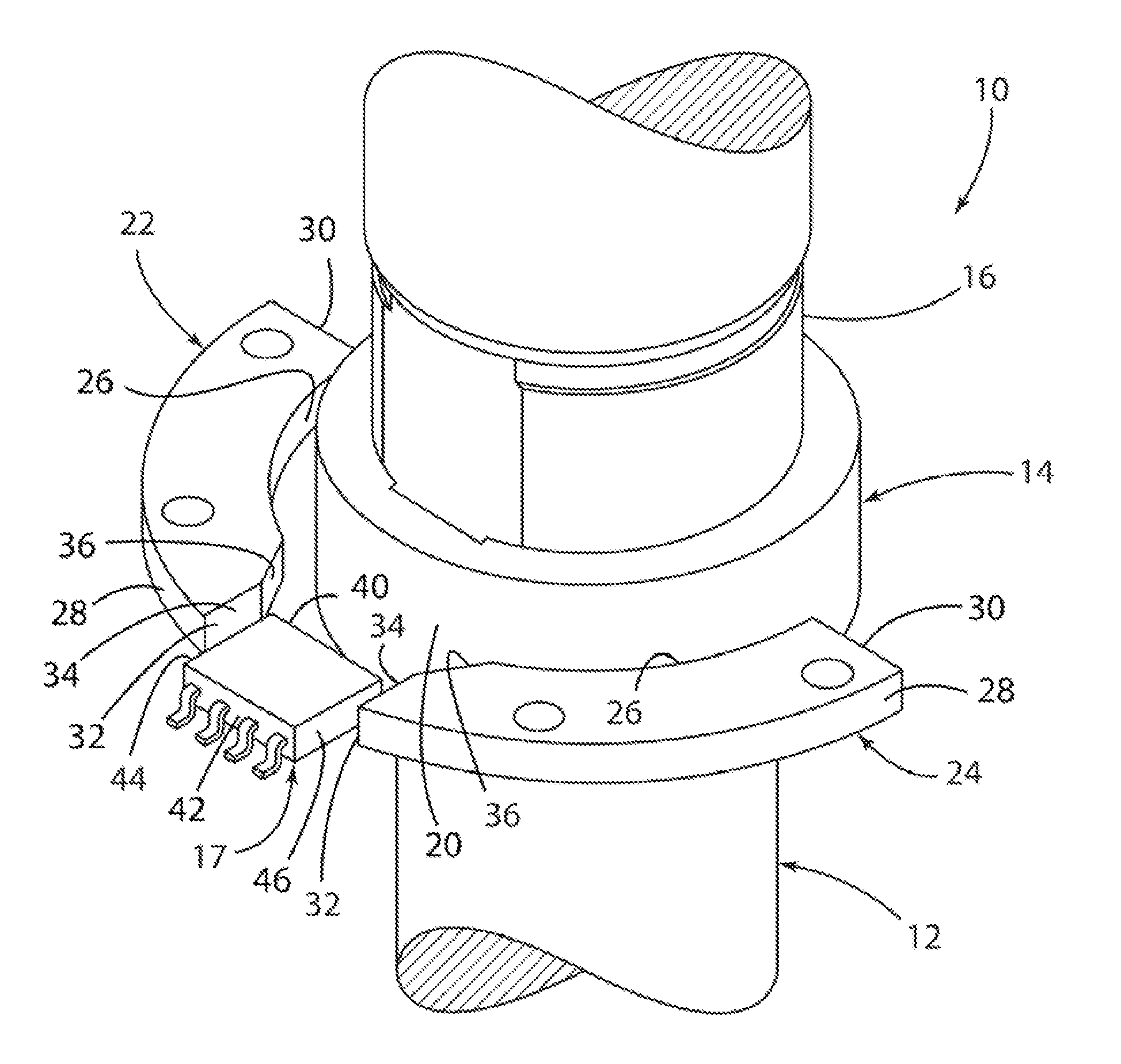
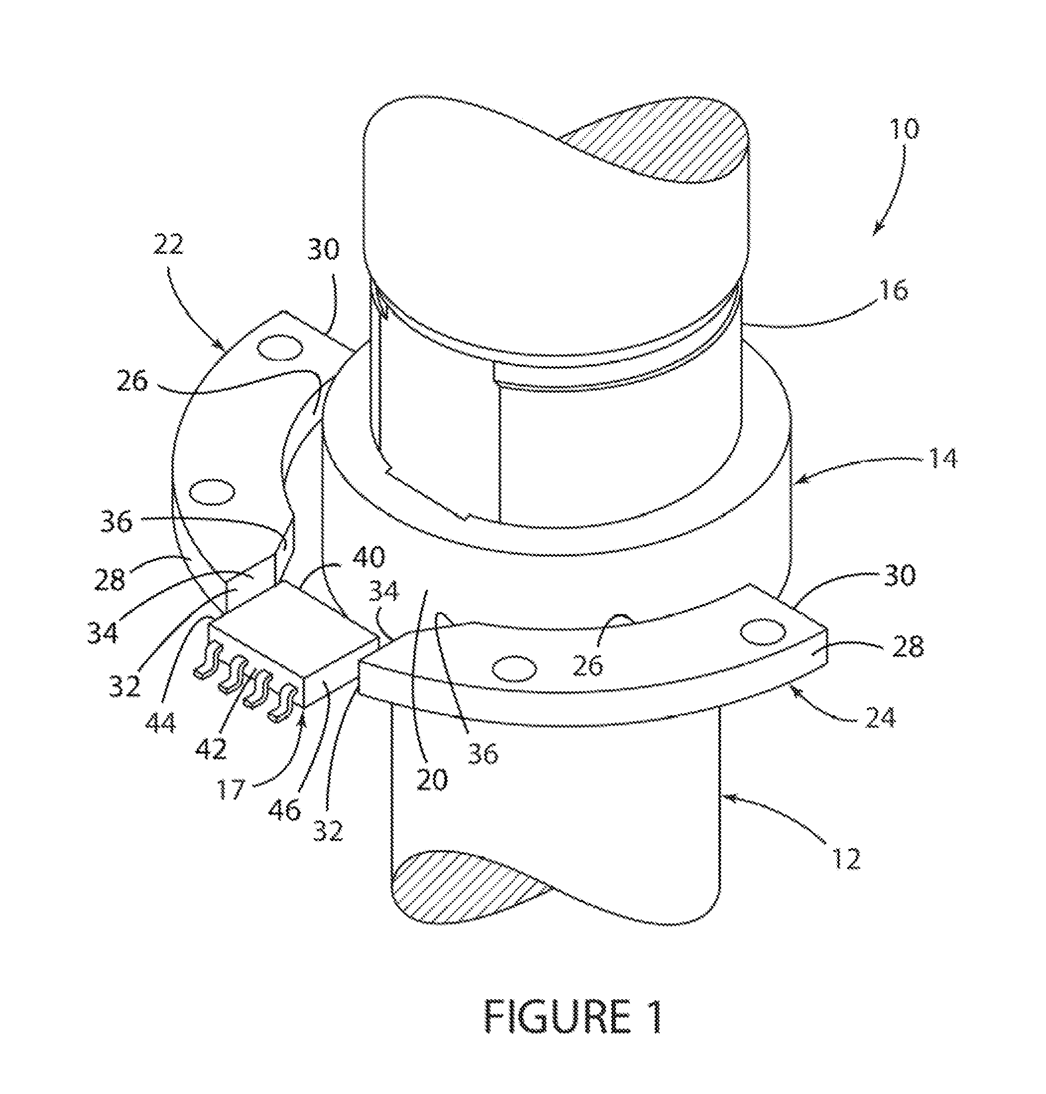
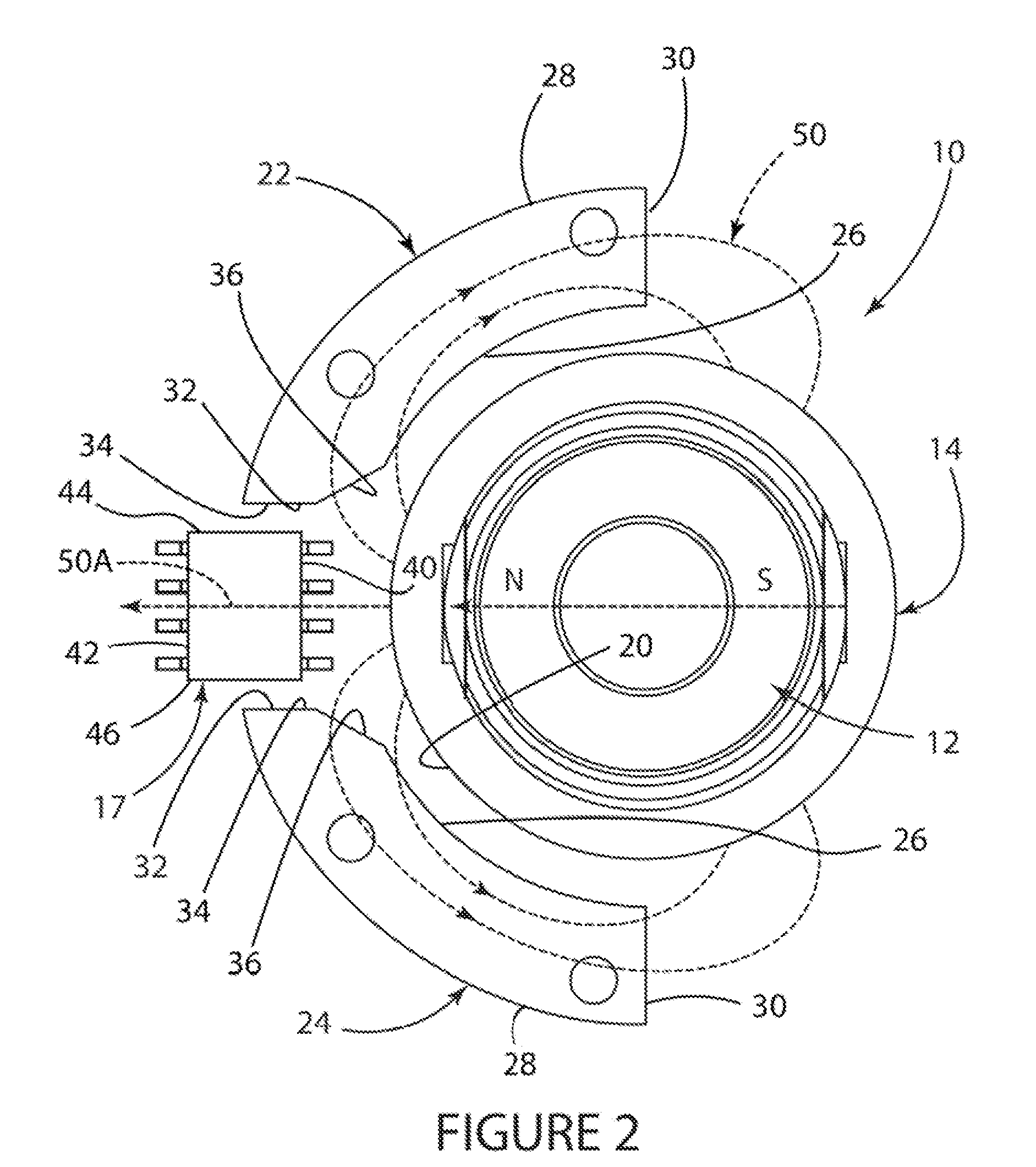
[0014]FIGS. 1-3 depict a simplified embodiment of a through shaft non-contacting rotary position sensor assembly 10 in accordance with the present invention which comprises at least the following key elements: an elongate, generally cylindrically-shaped through shaft 12 adapted for coupling to a part (not shown) whose rotary or angular position is required to be measured; a ring magnet 14 surrounding and coupled to the exterior circumferential surface 16 of the through shaft 12; a Hall effect sensor integrated circuit chip 17 located opposite and spaced from the exterior circumferential surface 20 of the ring magnet 14 and positioned in a relationship generally co-planar with the horizontal cross-sectional axis of the ring magnet 14; and a pair of generally curvilinearly-shaped magnet pole pieces 22 and 24 located opposite and spaced from the exterior surface 20 of the ring magnet 14 and positioned in a relationship generally co-planar with both the horizontal cross-sectional axis o...


PUM


Abstract

A rotary position sensor assembly includes a ring magnet extending around the outer surface of a rotatable through shaft. A sensor which measures changes in the direction of the magnetic flux generated by the magnet in response to rotation of the shaft and a pair of magnet pole pieces are located opposite and spaced from the magnet. The sensor is located between the pair of pole pieces and the pole pieces conduct the magnetic flux over the sensor and nominalize the strength of the magnetic flux sensed by the sensor over the full range of rotation of the shaft relative to the sensor.

Description

CROSS-REFERENCE TO RELATED APPLICATION[0001]This application claims the benefit of the filing date and disclosure of U.S. Provisional Application Ser. No. 61 / 281,132 filed on Nov. 13, 2009 which is explicitly incorporated herein by reference as are all references cited therein.FIELD OF THE INVENTION[0002]This invention relates to a rotary position sensor assembly and, more specifically, to a non-contacting rotary position sensor assembly using a Hall effect sensor.BACKGROUND OF THE INVENTION[0003]Non-contacting rotary position sensor assemblies which are available today for detecting and measuring the rotary position of an object include a magnet and a Hall effect sensor adapted to sense the direction of the magnetic field generated by the magnet in two dimensions. The use of this type of Hall effect sensor is becoming increasingly common for detecting the angle or position of the shaft of the rotary position sensor where the magnet can be mounted to one of the distal end surfaces o...

Claims


Application Information

Patent Timeline
IPC IPC(8): G01B7/30
CPCG01D5/145
Inventor BLAKESLEY, PATRICK B.
Owner CTS CORP ELKHART
Why Eureka
Try Eureka