Eureka AIR delivers breakthrough ideas for toughest innovation challenges, trusted by R&D personnel around the world.

Frequency calibration device and method for programmable oscillator

a programmable oscillator and frequency calibration technology, applied in the direction of pulse automatic control, generating/distributing signals, instruments, etc., can solve the problems of increasing system cost and the way usually takes longer calibration tim

Active Publication Date: 2011-05-19
PIXART IMAGING INC
View PDF1 Cites 0 Cited by
  • Summary
  • Abstract
  • Description
  • Claims
  • Application Information

AI Technical Summary

Benefits of technology

[0009]An object of the present disclosure is to provide a frequency calibration device and method for a programmable oscillator that can calibrate the oscillation frequency of the programmable oscillator during data transmission to prevent the frequency drift of the programmable oscillator caused by environmental changes.
[0010]The present invention provides a frequency calibration method for a programmable oscillator including the steps of receiving a clock signal and a USB data stream; estimating an accumulated bit number of the USB data stream according to the clock signal and counting an oversampling number of the clock signal; comparing the oversampling number and M times of the accumulated bit number when the accumulated bit number is larger than or equal to a predetermined value; decreasing the frequency of the clock signal when the oversampling number is larger than the M times of the accumulated bit number; and increasing the frequency of the clock signal when the oversampling number is smaller than the M times of the accumulated bit number.

Problems solved by technology

However, the external precise clock component not only increases the system cost, the control chip of the oscillation circuit also needs one or two extra pins to be served as a communication interface to the precise clock component.
However, this method usually takes longer calibration time and thus is adapted to certain applications, such as USB devices.

Method used


Image

  • Frequency calibration device and method for programmable oscillator
  • Frequency calibration device and method for programmable oscillator
  • Frequency calibration device and method for programmable oscillator

Examples


Embodiment Construction

[0024]It should be noticed that, wherever possible, the same reference numbers will be used throughout the drawings to refer to the same or like parts.

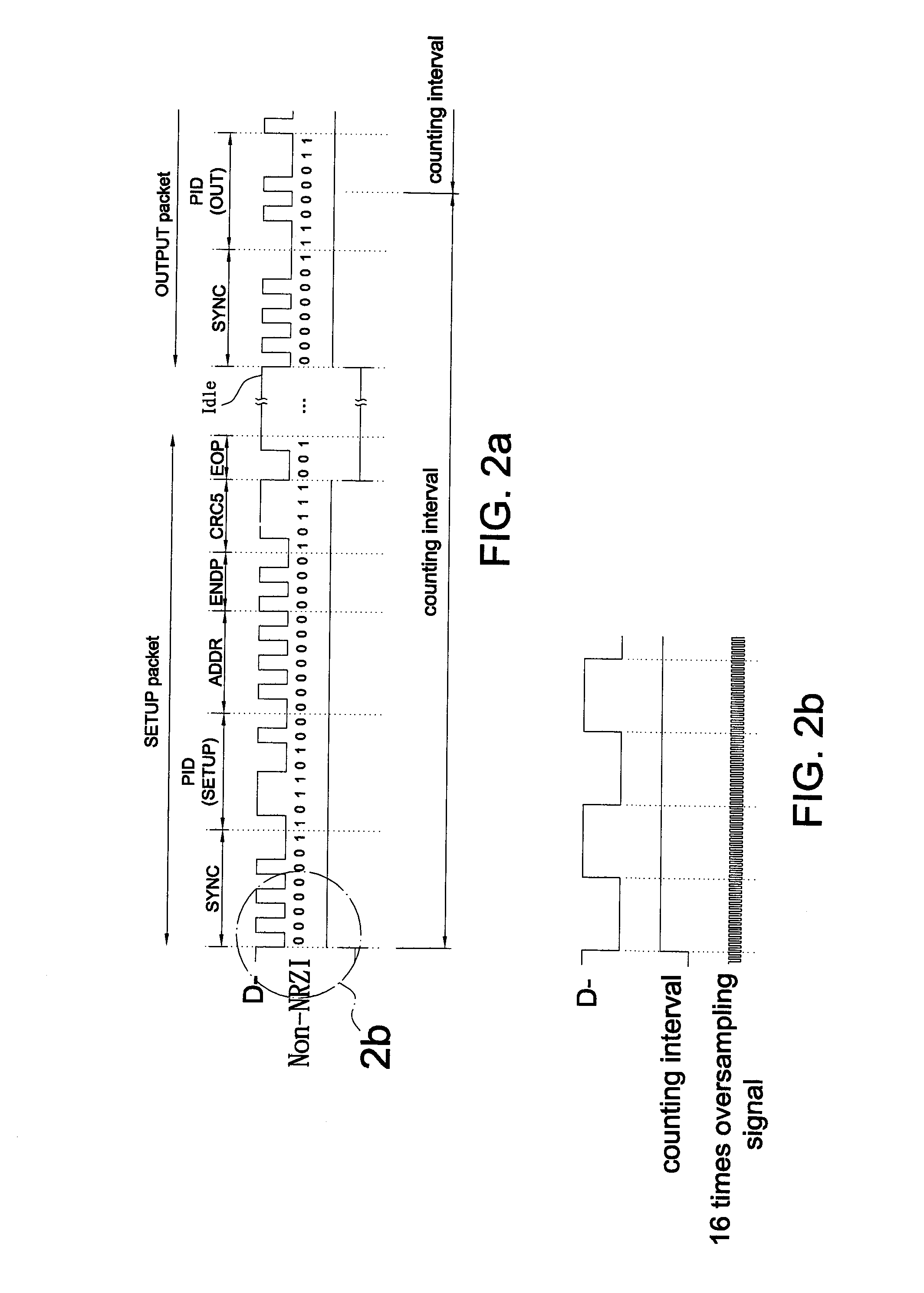
[0025]According to the Universal Serial Bus Specification revision 1.1, the data rate tolerance for a low-speed USB device functioning normally is within ±1.5%, and including the data error of a USB host ±0.25% the data rate tolerance for a built-in oscillator in the low-speed USB device should be within ±1.25% for ensuring a USB interface functioning correctly. Therefore, if the oversampling frequency of a USB device is 24 MHz (i.e. 16 times oversampling ratio), the oscillation frequency of a built-in oscillator in the USB device has to be ranged within 24 MHz±300 KHz. It is appreciated that the oversampling frequency of a USB device is not limit to 24 MHz.

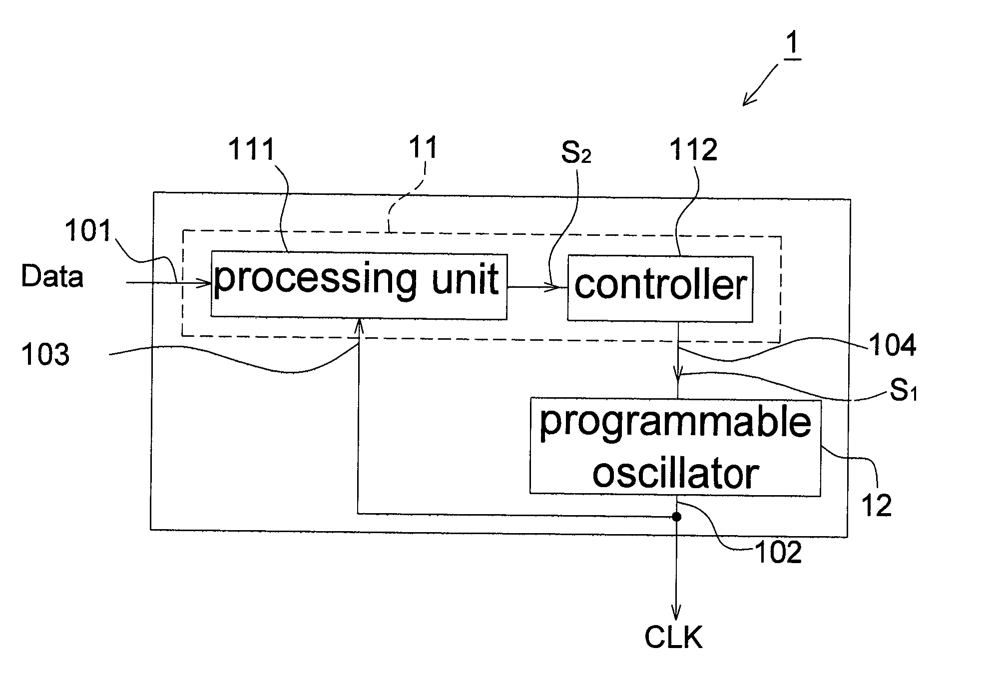
[0026]Please refer to FIG. 1, it shows a self-calibrating oscillator circuit 1 according to an embodiment of the present invention, which includes an input terminal 101 and an outp...


PUM


Abstract

A frequency calibration method for a programmable oscillator includes the steps of: counting an oversampling number of an oversampling signal and estimating an accumulated bit number of a USB data stream according to the oversampling signal; calculating a difference between the oversampling number and M times of the accumulated bit number when the accumulated bit number is larger than or equal to a predetermined value; and determining a frequency calibration step of the oversampling signal according to the difference. The present invention further provides a frequency calibration device for a programmable oscillator.

Description

CROSS REFERENCE TO RELATED APPLICATION[0001]This application claims the priority benefit of Taiwan Patent Application Serial Number 098139076, filed on Nov. 18, 2009, the full disclosure of which is incorporated herein by reference.BACKGROUND[0002]1. Field of the Invention[0003]This invention generally relates to a data transmission structure and method and, more particular, to a frequency calibration device and method for automatically calibrating the oscillation frequency of a programmable oscillator according to a data stream.[0004]2. Description of the Related Art[0005]An oscillation circuit with external clock can be used to provide a clock signal, and the oscillation circuit conventionally uses an external precise clock component, such as a crystal resonator or a ceramic resonator, to provide a reference frequency to the oscillation circuit. However, the external precise clock component not only increases the system cost, the control chip of the oscillation circuit also needs ...

Claims


Application Information

Patent Timeline
IPC IPC(8): H03L7/00
CPCH03L7/099H03L7/0807
Inventor WU, CHIH YENHUANG, CHIEN JUNGLIU, HSIANG SHENGCHEN, CHING CHIH
Owner PIXART IMAGING INC
Why Eureka
Eureka Blog
Learn More