Insulation displacement terminal, splicing terminal assembly and press-contact structure for electric cable

a technology of splicing terminal and electric cable, which is applied in the direction of contact members penetrating/cutting insulation/cable strands, connection contact material, electrical equipment, etc., can solve the problem of increasing electrical resistance and achieve the effect of increasing electrical resistan

Inactive Publication Date: 2011-05-19
SUMITOMO WIRING SYST LTD
View PDF11 Cites 19 Cited by
  • Summary
  • Abstract
  • Description
  • Claims
  • Application Information

AI Technical Summary

Benefits of technology

[0026](9) The covered electric cable is an aluminium electric cable in which an insulation sheath covers a core wire comprising a plurality of aluminium or aluminium alloy strands. This is particularly effective for the aluminium electric cable that is likely to generate a

Problems solved by technology

Consequently, there is a problem that an electrical resistance will be increased in a press-contact portion be

Method used


Image

  • Insulation displacement terminal, splicing terminal assembly and press-contact structure for electric cable
  • Insulation displacement terminal, splicing terminal assembly and press-contact structure for electric cable
  • Insulation displacement terminal, splicing terminal assembly and press-contact structure for electric cable

Examples


first embodiment

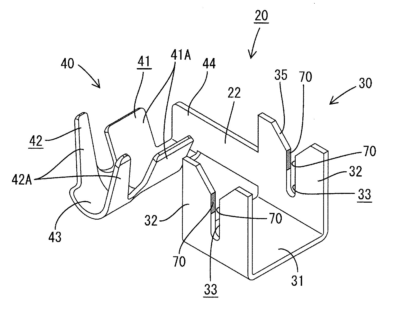
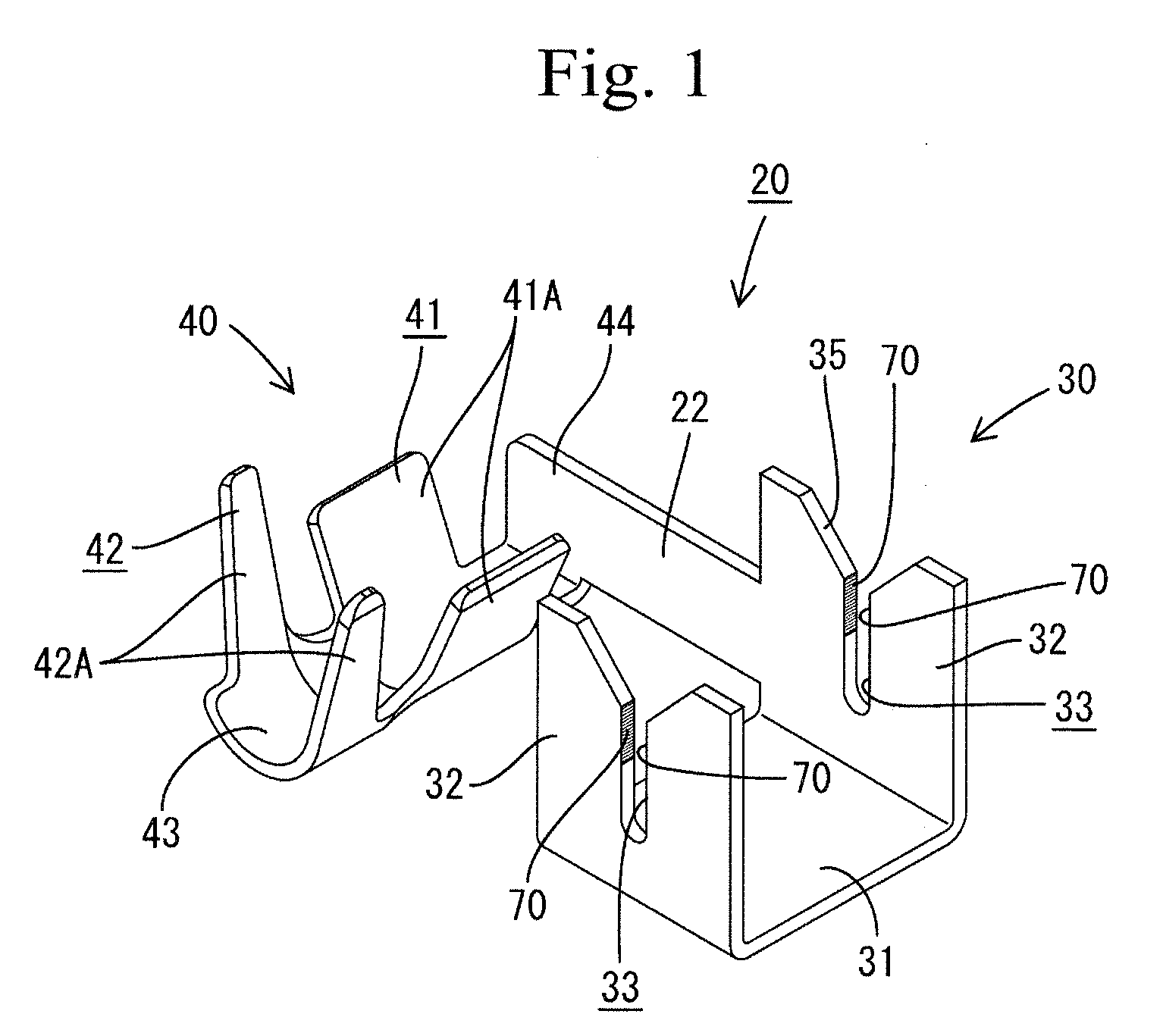
[0039]FIGS. 1 to 8 show a first embodiment of a splicing terminal assembly 20 in accordance with the present invention.

[0040]The first embodiment illustrates a case where a main line such as an electrical power sourced line is branched into and connected to a signal line for an air bag system or the like. An insulation displacement terminal 30 according to the present invention is applied to a part of the splicing terminal assembly 20 suitable for branching connection.

[0041]The main line uses an aluminium electric cable 10. As shown in FIG. 4, the aluminium electric cable 10 includes a core wire 11 formed by a plurality of strands made of aluminium or aluminium alloy. The core wire 11 is covered with a synthetic resin insulation sheath 13. FIGS. 4 to 6 show schematically a cross section of the core wire 11 comprising a plurality of aluminium strands, as a whole.

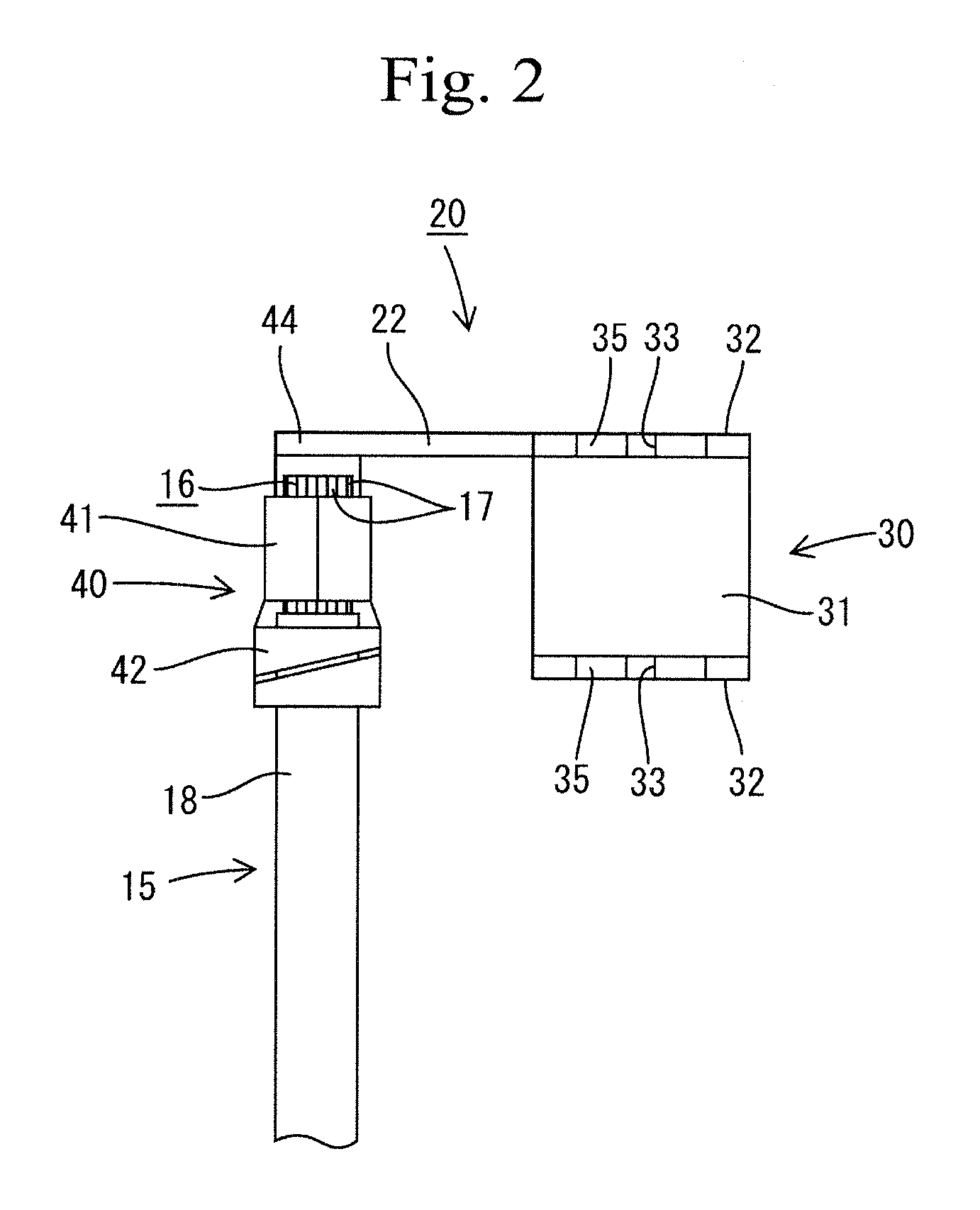
[0042]A branched line uses a copper electric cable 15. As shown in FIG. 2, the copper electric cable 15 includes a core wir...

second embodiment

[0072]A second embodiment of the splicing terminal assembly 20 in accordance with the present invention will be described below by referring to FIG. 9.

[0073]As described in the first embodiment, the splicing terminal assembly 20 is used for the main line aluminium electric cable 10, and the copper electric cable 15 is branched from the main line aluminium electric cable 10 through the splicing terminal assembly 20. In particular, if a portion of the aluminium electric cable 10 that is press-contacted with the insulation displacement terminal in the splicing terminal assembly 20 is located under a hard condition in which cooling and heating actions are repeated at a mounting position of a wire harness, the core wire 11 of the aluminium electric cable 10 repeats contraction and expansion. In particular, when the core wire 11 is contracted, a gap is caused between the core wire 11 and the groove edges 34 of the press-contact grooves 33, thereby involving a possibility that another cont...

third embodiment

[0077]FIG. 10 shows a third embodiment of the splicing terminal assembly in accordance with the present invention. Generally, the insulation displacement terminal 30 is formed by cutting and bending a copper or copper alloy plate into a given shape by a press machine. Then, the terminal 30 is dipped in molten tin (Sn) to plate the terminal 30.

[0078]In the third embodiment, an approximately half area 80 of the right and left groove edges 34 of the press-contact grooves 33 in the press-contact blades 32 near the guide portion 35 is masked before plating. Accordingly, the groove edges 34 on the area 80 are left as originally cut surfaces. In result, stripping portions 81 are provided with relatively rough surfaces.

[0079]According to the third embodiment, when the insulation sheath 13 of the aluminium electric cable 10 is broken by the press-contact grooves 33 in the press-contact blades 32 to expose the core wire 11 and the exposed core wire 11 is pushed down into the grooves 33, first...


PUM


Abstract

A terminal fitting (10) includes a main body (20) to be coupled to a mating conductor, and a crimp contact section (30) rearward from the main body (20). The crimp contact section (30) is crimped on an end of a core wire (42) in a covered electrical cable (40) so as to surround the end. The core wire (42) includes a plurality of metallic strands (41) and is covered with a sheath (43) to form the covered electrical cable (40). Serrations (34) are provided on a contact surface of the crimp contact section (30) for surrounding the core wire (42). Each serration (34) is a polygonal shaped recess with which the core wire (42) engages upon crimping. Both diagonal corner portions (34C) of each serration (34) are rounded. Thus, the whole periphery of an opening edge around the recess penetrates an oxide layer on a core wire.

Description

BACKGROUND OF THE INVENTION[0001]1. Field of the Invention[0002]This invention relates to an insulation displacement terminal, a splicing terminal assembly, and a press-contact structure for an electric cable.[0003]2. Description of the Related Art[0004]Heretofore, for example an insulation displacement terminal has been utilized as a splicing terminal assembly for branching a branched line from a main line and connecting the branched line to the main line or a jointing terminal assembly for connecting a plurality of electrical cables (see, for example, JP HEI 10 (1998)-275639 A.[0005]The insulation displacement terminal is formed by pressing a metallic plate having high electrical conductivity. The insulation displacement terminal includes a press-contact blade provided with a press-contact groove. A covered electric cable in which a conductive core wire is covered with an insulation sheath is pushed into the press-contact groove. When the covered electric cable is pushed into the ...

Claims


Application Information

Patent Timeline
IPC IPC(8): H01R4/24
CPCH01R4/185H01R4/62H01R4/2454
Inventor OKAMURA, KENJITABATA, MASAAKI
Owner SUMITOMO WIRING SYST LTD
Why Eureka
Try Eureka