Pedometer with shoe mounted sensor and transmitter

a pedometer and transmitter technology, applied in the field of pedometers, can solve the problems of inability to accurately measure the switch is prone to contamination in situ, and the accuracy of the pedometer is adversely affected, so as to reduce the false step count reading, reduce the false step count, and improve the accuracy.

Active Publication Date: 2011-05-19
SILICON VALLEY MICRO C
View PDF12 Cites 61 Cited by
  • Summary
  • Abstract
  • Description
  • Claims
  • Application Information

AI Technical Summary

Benefits of technology

[0009]The invention comprises a pedometer which is devoid of the above-noted disadvantages, which substantially reduces false s

Problems solved by technology

While somewhat useful, pedometers using a pendulum to detect steps frequently record “false steps” or erroneous movements such as bending over and leaning.
Moreover, pendulum actuated pedometers are sensitive to proper vertical alignment and usually require mechanical adjustment in relation to the gait/stride of the user in order to accurately record steps and convert the number of steps to a distance value.
Further, the switches are prone to contamination in situ and are susceptible to wear given the harsh environment in which they are located.
Additionally, improper axial alignment of the accelerome

Method used


Image

  • Pedometer with shoe mounted sensor and transmitter
  • Pedometer with shoe mounted sensor and transmitter
  • Pedometer with shoe mounted sensor and transmitter

Examples


Embodiment Construction

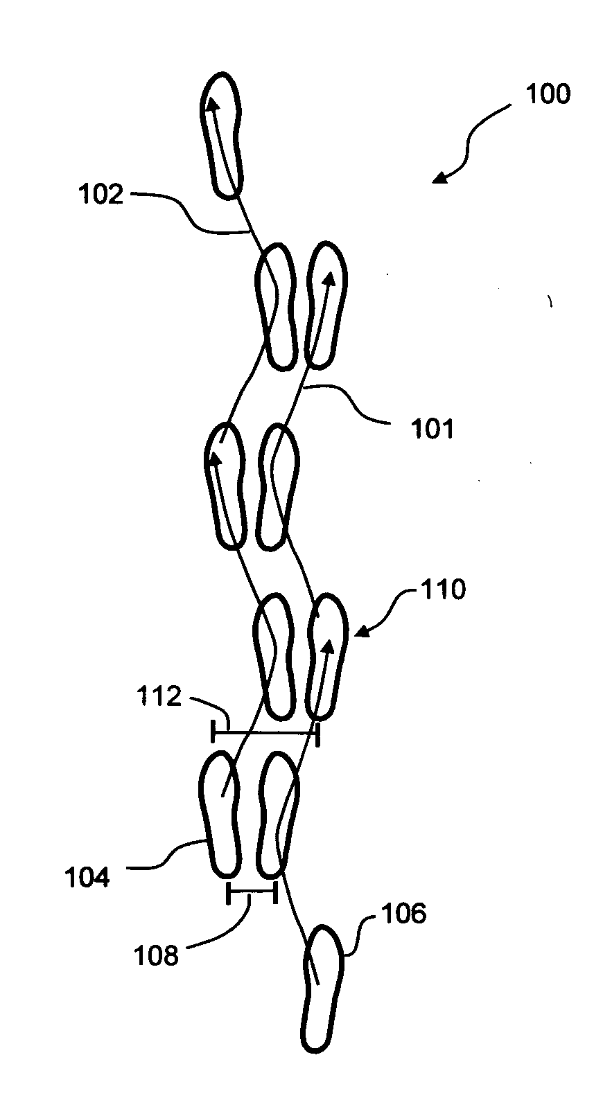
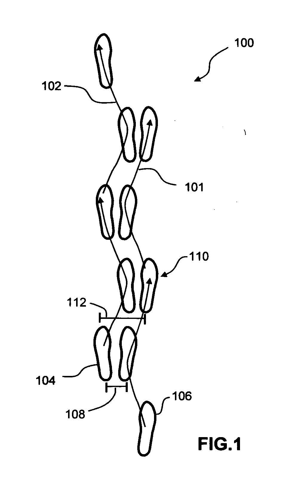
[0023]Turning now to the drawings, FIG. 1 is a schematic view of a typical bipedal walk cycle 100. As seen in this Fig., a typical human or bipedal walk cycle 100 for generally linear forward motion incorporates a right foot sinuous path 101 and a left foot sinuous path 102. When both the right and left foot sinuous paths 101, 102 are combined, a biped walk cycle 100 producing forward generally linear motion is achieved. To begin a walk cycle 100, a forward foot 104 carries the majority of the weight of a person. The rearward foot 106 is then lifted and moved in a generally forward direction, as indicated by the directional arrows. As the rearward foot 106 moves towards the forward foot 104, the motion of rearward foot 106 curves inwards towards the forward foot 104 to form an arcuate path. A minimum interspatial distance 108 between the two feet 104, 106 is defined when the initially forward foot 104 and the initially rearward foot 106 achieve a minimum separation distance. At this...


PUM


Abstract

A pedometer has first and second signal generators mounted along the inner margin of a first shoe and separated by a fixed distance. A sensor and transmitter assembly is mounted along the inner margin of a second shoe. The sensor and transmitter assembly includes a sensor, a microcontroller unit and a wireless transmitter. A pair of impulses is received by the microcontroller unit each time the shoes pass in close proximity to each other. The microcontroller unit generates various pedestrian performance data based on the impulses. The pedestrian performance data is wirelessly transmitted to a display unit carried by the pedestrian.

Description

BACKGROUND OF THE INVENTION[0001]This invention relates to pedometers used to measure pedestrian step counts and calculate distances traveled on foot. More particularly, this invention relates to a pedometer that comprises a shoe mounted system that acquires pedestrian performance data and transmits calculated results to a separate display unit.[0002]Pedometers are being increasingly used by both professional and amateur fitness enthusiasts as an aid in monitoring and evaluating exercise routines. By using a pedometer, a person can measure and record a variety of data parameters, such. as: step count, distance traveled, speed, and calories burned to name a few. These parameters are useful in determining the effectiveness and efficiency of a particular fitness program. Additionally, a pedometer may be used as a motivational device by providing a person with a way to track their daily physical activity level and correspondingly establish increased activity level targets. The use of a ...

Claims


Application Information

Patent Timeline
IPC IPC(8): G01C22/00
CPCG01C22/006
Inventor ZHU, SHENGBOHUANG, SU SHIONG
Owner SILICON VALLEY MICRO C
Why Eureka
Try Eureka