Wellbore instruments using magnetic motion converters

a technology of magnetic motion converter and wellbore, which is applied in the direction of survey, directional drilling, and borehole/well accessories. it can solve the problems of limiting the depth in which wellbore instruments can be used when considering the total system fluid pressure loss, vibration from the device is conducted to other supporting elements associated with the device, and vibration damag

Active Publication Date: 2011-05-26
SCHLUMBERGER TECH CORP
View PDF15 Cites 43 Cited by
  • Summary
  • Abstract
  • Description
  • Claims
  • Application Information

AI Technical Summary

Benefits of technology

[0007]A directional drilling apparatus according to one aspect of the invention includes a housing configured to couple to a drill string. A plurality of magnets is disposed in the housing and is configured to convert rotation to reciprocating motion. The magnets are configured to impart impacts to the housing by the reciprocating motion. A motor coupled to the magnets to apply rotation to a part thereof. A control system is configured to operate the motor such that the impacts occur when the housing is in a selected rotational orientation.

Problems solved by technology

One of the drawbacks inherent in reciprocating motion devices is that vibration from the device is conducted to other supporting elements associated with the device, e.g., portions of a drilling tool assembly (tool “string”).
Such vibration can be damaging, particularly when there are sensitive electronic devices located near the reciprocating device, which is usually the case with tools such as directional drilling assemblies and logging while drilling (“LWD”) tools.
Hammer drills such as the one disclosed in the Cyphelly '690 patent also typically have high fluid pressure losses associated with them, which can limit the wellbore depth in which they can be used when considering the total system fluid pressure losses.

Method used


Image

  • Wellbore instruments using magnetic motion converters
  • Wellbore instruments using magnetic motion converters
  • Wellbore instruments using magnetic motion converters

Examples


Embodiment Construction

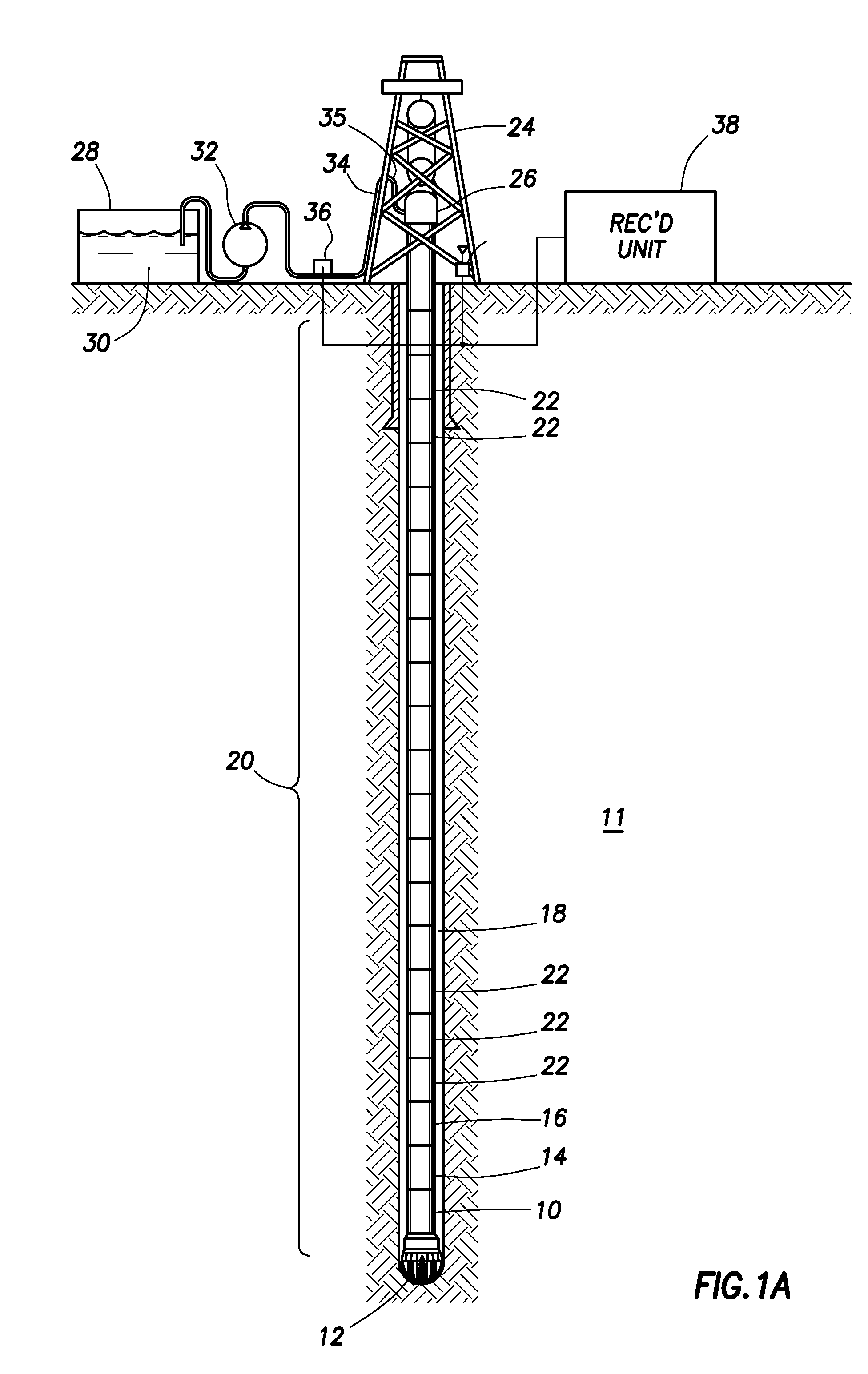
[0030]FIG. 1A shows a wellbore drilling system to illustrate possible uses for example devices according to the various aspects of the invention. In FIG. 1A, a drilling rig 24 or similar lifting device suspends a conduit called a “drill string 20” within a wellbore 18 being drilled through subsurface rock formations 11. The drill string 20 may be assembled by threadedly coupling together end to end a number of segments (“joints”) 22 of drill pipe. The drill string 20 may include a drill bit 12 at its lower end. When the drill bit 12 is axially urged into the formations 11 at the bottom of the wellbore 18 by the weight of the drill string 20, and when the bit 12 is rotated by equipment (e.g., top drive 26) on the drilling rig 24 turning the drill string 20, such urging and rotation causes the bit 12 to axially extend (“deepen”) the wellbore 18. The lower end of the drill string 20 may include, at a selected position above and proximate to the drill bit 12, a directional drilling stee...


PUM


Abstract

A directional drilling system, a drilling hammer and a fluid flow telemetry modulator use a plurality of magnets arranged to convert rotational motion into reciprocating linear motion. Various types of motor can provide rotational motion to a part of the magnets and various linkages and other devices can cause steering or operation of a modulator valve. A torsional drilling hammer uses a plurality of magnets arranged to convert reciprocating linear motion into reciprocating rotational motion. A motor and linkage drives the linearly moving part of the magnets, and the rotating part provides torsional impact be striking the linearly moving part of the magnets.

Description

BACKGROUND OF THE INVENTION[0001]1. Field of the Invention[0002]The invention relates generally to the field of magnetic motion converters. More particularly, this invention relates to uses for a device that converts rotary motion into axial motion by magnetic interactions, and applications of such devices in wellbore instruments.[0003]2. Background Art[0004]Wellbore drilling and servicing instrumentation includes percussion devices. Percussion devices include drilling “hammers” that convert flow of drilling fluid or rotational motion into reciprocating linear motion to cause a hammer bit or similar device to strike the bottom of the wellbore. The striking motion at least in part causes the wellbore to be lengthened. See, for example, U.S. Pat. No. 4,958,690 issued to Cyphelly. The device disclosed in the Cyphelly '690 patent converts flow of drilling fluid into reciprocating linear motion.[0005]Typical reciprocating motion devices use eccentric rotation, e.g., camshafts, or use var...

Claims


Application Information

Patent Timeline
Patent Type & Authority Applications(United States)
IPC IPC(8): E21B34/06E21B4/00E21B10/00E21B7/04E21B7/00H02K49/10
CPCE21B4/06E21B1/00E21B47/18E21B7/24
Inventor DOWNTON, GEOFFREY C.COOPER, IAINWILLIAMS, MIKEUTTER, ROBERT
Owner SCHLUMBERGER TECH CORP
Why Eureka
Try Eureka