Method and device for dispensing a liquid

a liquid and liquid technology, applied in the direction of liquid dispensing, liquid/fluent solid measurement, opening closed containers, etc., can solve the problems of increased essential maintenance, difficult cleaning, and high level of maintenance of the device, and achieve the effect of limiting resistance, relatively quick supply and relatively quick supply

Active Publication Date: 2011-05-26
DE GROOD INNOVATIONS
View PDF3 Cites 12 Cited by
  • Summary
  • Abstract
  • Description
  • Claims
  • Application Information

AI Technical Summary

Benefits of technology

[0010]A wall of the container in which the dispensing openings are incorporated preferably extends connecting to the dispensing opening over more than 50%, and in an ideal case 100%, of the opening in the plane of the opening so as to thus create the most limited resistance possible during liquid passage. It is most advantageous here if the dispensing openings connect over their full periphery to the liquid container. A connection over a substantial part of the periphery to the liquid container has the additional advantage that the supply of the liquid can take place relatively quickly. Viscous liquid can thus for instance also be supplied relatively quickly.
[0012]In a further embodiment of the device according to the present invention a wall of the container is provided with dispensing openings and the device is provided with individual parallel liquid channels connecting the liquid container to the dispensing openings. The number of channels is here for instance equal to the number of dispensing openings, one channel can lead the liquid to a plurality of dispensing openings or, conversely, a plurality of channels can lead the liquid to one dispensing opening. The dispensing openings are isolated from each other by arranging the channels, thereby reducing unevenness in the dispensing of the liquid from a determined dispensing opening as a result of interference between this dispensing opening and adjacent or nearby dispensing openings.

Problems solved by technology

Due to its complex construction with narrow feed channels, cylinders and pistons, it is difficult to clean, which represents a problem because of the strict hygiene requirements in for instance the processing of food products.
In addition, there is a possibility of the liquid solidifying in the channels, whereby the device requires a high level of maintenance.
This essential maintenance is increased still further here due to the great wear of the plunger and nozzle as a result of the moving parts.
This device however also has the drawback that dispensing of an accurate, very small quantity of liquid, in the order of magnitude of a droplet, is not possible herewith due to the large liquid storage capacity of the supply and discharge channel and the high resistance the channel provides to the liquid.
Due to the force exerted thereon the membrane is further subject to great wear, which makes the embodiment susceptible to wear.
Moreover, ES 1 191 528 does not disclose one device having a plurality of dispensing openings.
However, the dispensing opening in the apparatus is continuously uncovered, so the liquid in the chamber cannot be placed under pressure.

Method used


Image

  • Method and device for dispensing a liquid
  • Method and device for dispensing a liquid
  • Method and device for dispensing a liquid

Examples


Embodiment Construction

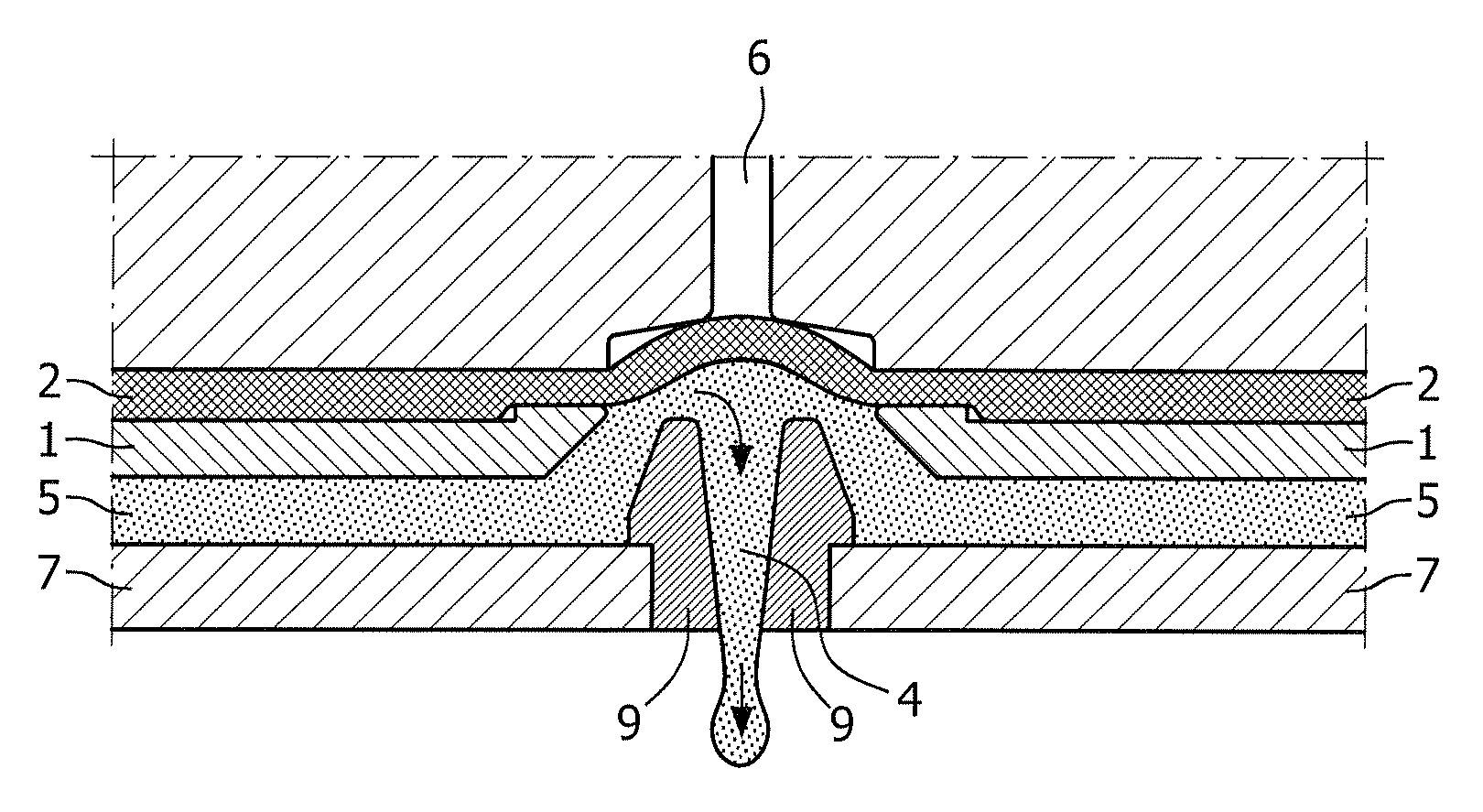
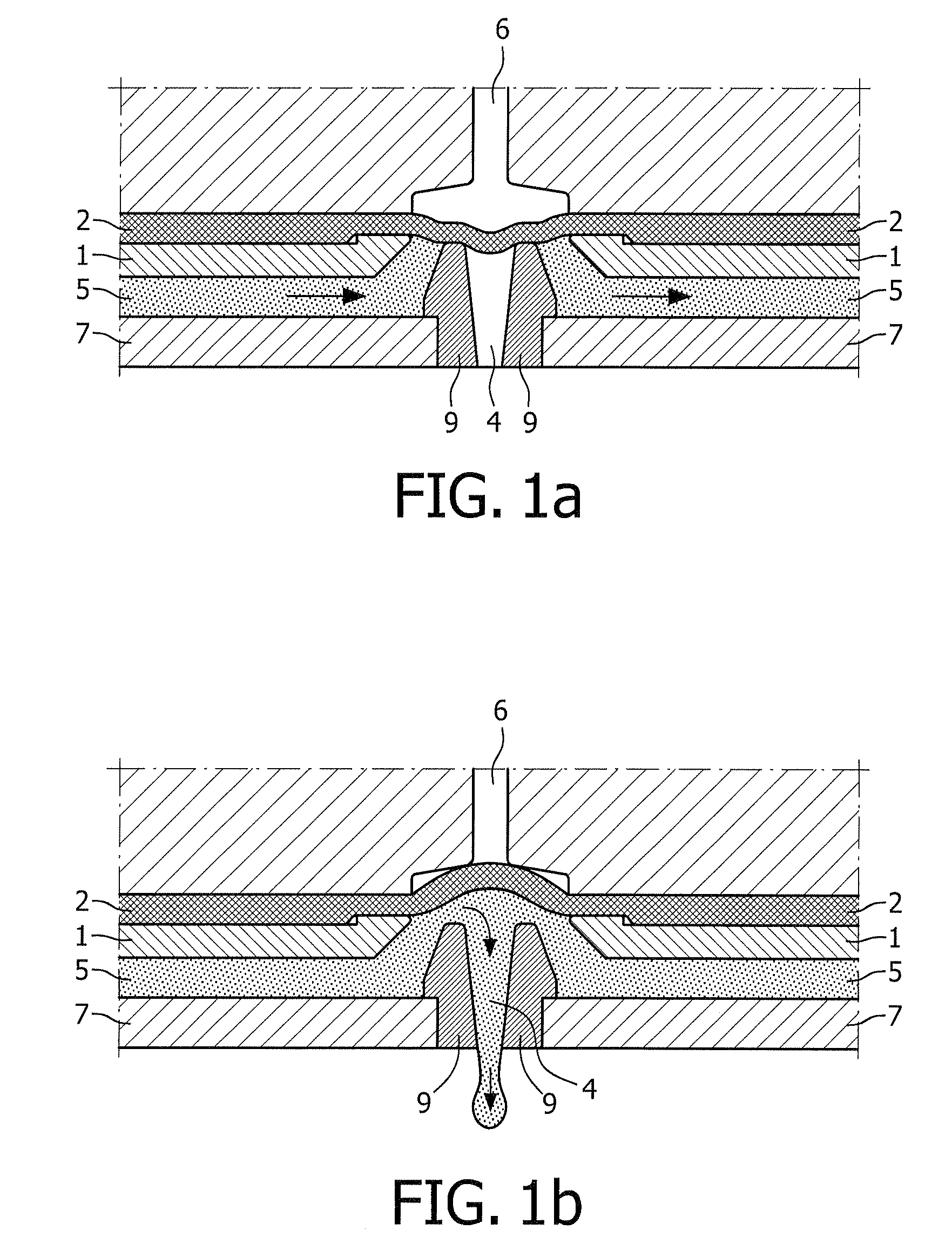
[0034]FIG. 1a shows a cross-section of a device according to the present invention. The figure shows upper wall 1 and a lower wall 7 of a container for containing a liquid 5. A discharge channel 4 for liquid 5 extends through lower wall 7. Discharge channel 4 is sealed by a closure formed by a membrane 2. Membrane 2 is pressed into a first position thereof by means of air pressure in chamber 6, in which position it seals channel 4 so that the liquid 5 cannot leave the reservoir. Channel 4 is formed in a spray nozzle 9 arranged in lower wall 7.

[0035]FIG. 1b shows a cross-section of a device according to the present invention of FIG. 1a, wherein membrane 2 is in a second position thereof. The figure again shows upper wall 1 and a lower wall 7 of a container for containing a liquid 5. Discharge channel 4 is now however left clear by the closure formed by membrane 2. Membrane 2 is pulled into a second position thereof by means of a low air pressure, or even a vacuum, in chamber 6, in wh...


PUM


Abstract

Device and method for dispensing a liquid, comprising a liquid container; a plurality of dispensing openings connecting to the liquid container for controlled dispensing of the liquid to a substrate, and at least one membrane which connects onto the dispensing openings and which is displaceable between a first sealing position, in which the dispensing openings are covered by the membrane, and a second opened position in which the dispensing openings are left clear by the membrane, which device is also provided with a medium-filled control system which connects to the membrane such that the membrane is displaceable between the first and the second position by means of pressure variation on the medium.

Description

[0001]The present invention relates to a method and device for dispensing a liquid. The invention relates particularly to arranging on a substrate a material layer of a different material, wherein both materials are for instance formed by food products. Alternatively, the materials can also be formed by a decorative enameling and tiles or the like. Adhesive can herein be applied for instance to specific adhesive surfaces in a manner such that products are for instance coated with polymer or varnish while leaving the edges clear (edge-free coated) so as to thus prevent fouling of a conveyor belt. More specific examples of this type of process are the arranging of a decorative filling or a surface decoration on cosmetics packages and the printing of pharmaceutical products.BACKGROUND OF THE INVENTION[0002]In the production of food products it may in some circumstances be advantageous or desirable to arrange a second food product on a substrate formed by at least one first food product...

Claims


Application Information

Patent Timeline
Patent Type & Authority Applications(United States)
IPC IPC(8): B67D7/06B67D7/00
CPCA23G3/28F16K11/022A23P2001/089A23P1/085A23P20/15A23P2020/253
Inventor DE GROOD, JOHANNES PETRUS WILHELMUSDE GROOD, PASCAL JOHANNES
Owner DE GROOD INNOVATIONS
Why Eureka
Try Eureka