Current mode digital control of the output voltage of a switching power supply

a technology of switching power supply and output voltage, which is applied in the direction of power conversion system, electric variable regulation, instruments, etc., can solve the problems of system inability to flyback converter, system inconvenient operation, and significant cost of voltage reference and photocoupler, so as to achieve precise control of output voltage, reduce the number of external components, and facilitate operation.

Active Publication Date: 2011-05-26
STMICROELECTRONICS SRL
View PDF12 Cites 39 Cited by
  • Summary
  • Abstract
  • Description
  • Claims
  • Application Information

AI Technical Summary

Benefits of technology

[0007]An object is to provide a control method that may address the above noted issues, inefficiencies and limitations of typical circuits, freeing the designer from providing an external reference voltage and an error amplifier (E / A) while allowing precise regulation of the output voltage in a simple manner using a reduced number of external components. Moreover, the technique of this disclosure may modulate the clamp current in function of the load, and therefore be usable even in flyback converters without causing any acoustic noise on the transformer. Another object is to make the circuit easily realizable within a commonly integrated control circuit.

Problems solved by technology

The use of a voltage reference and of a photo-coupler implies a significant cost, and the alternative embodiment of using a bipolar Zener diode may make the system less precise because of a significantly larger tolerance of the reference and of “spread” of parameters in function of temperature (that may only partially be nullified by realizing specific compensation circuits).
However, because the switching cycle starts always at the maximum clamp current, even at very small loads only when the average switching frequency varies, the system is not suitable for flyback converters, because acoustic noise may be generated on the transformer at low output load conditions.

Method used


Image

  • Current mode digital control of the output voltage of a switching power supply
  • Current mode digital control of the output voltage of a switching power supply
  • Current mode digital control of the output voltage of a switching power supply

Examples


Embodiment Construction

[0020]Exemplary embodiments of the claimed invention are described referring to the attached drawings. Schemes and incremental numbers used for practicing the invention may be different and may be chosen by the designer depending on preferences and specific needs of the envisaged application. Therefore, this invention is not limited to the exemplary embodiments herein illustrated and described.

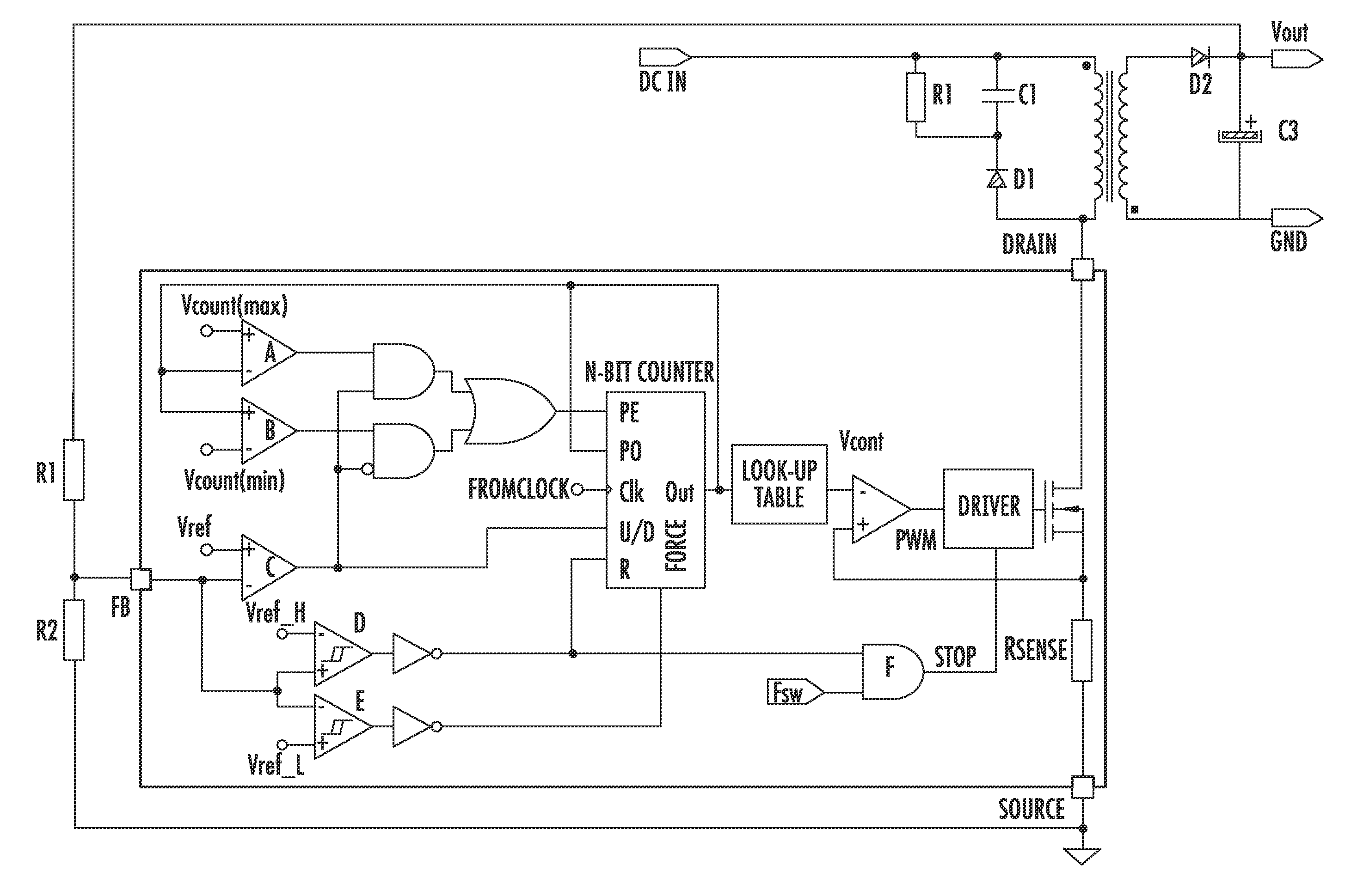
[0021]An exemplary high level block diagram that shows a possible circuit implementation of the control method in current mode is shown in FIG. 4. Basically, the device comprises: 1) an input comparator C, the non inverting pin of which is connected to a constant reference voltage VREF, and the other pin is externally connectable; 2) a N-bit up / down counter (N-bit counter) the output of which is incremented or decremented by one unit depending on the output state of the comparator C at each leading edge of the clock signal CK applied to the counter through the same name input; the input R rese...


PUM


Abstract

A method of controlling an output voltage of a pulse width modulation (PWM) converter with a PWM signal driving a power switch of the converter may include using a comparator to compare a reference voltage with a scaled output voltage of the converter, incrementing or decrementing an up/down counter at each pulse of a clock signal applied to the counter depending on a state of the comparator, and controlling the comparator to generate the PWM signal with a control voltage selected from a look-up table using a value of the counter.

Description

FIELD OF THE INVENTION[0001]This present disclosure relates to switching power supplies and, in particular, to control circuits of converters used in switched-mode power supplies for regulating the output of the power supply.BACKGROUND OF THE INVENTION[0002]In converters, the output voltage should remain constant even in the presence of fluctuations of the input voltage, the load, and the parameters, such as temperature and spread of the values of components. This has been achieved by using a closed loop regulation technique. Current mode control is very commonly used, and a typical implementation block diagram is shown in FIG. 1. The output voltage of the converter, or more often a scaled fraction thereof, is compared with a reference value VREF, and the difference is amplified by an error amplifier E / A.[0003]The amplified signal is compared with information coming from the current sensing resistor RSENSE and is processed by an appropriate driver. With this technique, the drain cur...

Claims


Application Information

Patent Timeline
Patent Type & Authority Applications(United States)
IPC IPC(8): H02M3/335
CPCH02M3/33515H02M3/157
Inventor CACCIOTTO, FABIO
Owner STMICROELECTRONICS SRL
Why Eureka
Try Eureka