With technology advances demanding ever increasing flexibility and connection speeds, installation, maintenance and upgrades of “loop” service to residences and industry is becoming an increasing problem.
Having a
technician test and hand wire connects and disconnects is labor intensive, costly, error prone, and can result in poor
documentation records,
poor quality, and low customer satisfaction.
Documentation and billing of such services and changes are resource and time demanding tasks with
record accuracy nigh unto impossible.
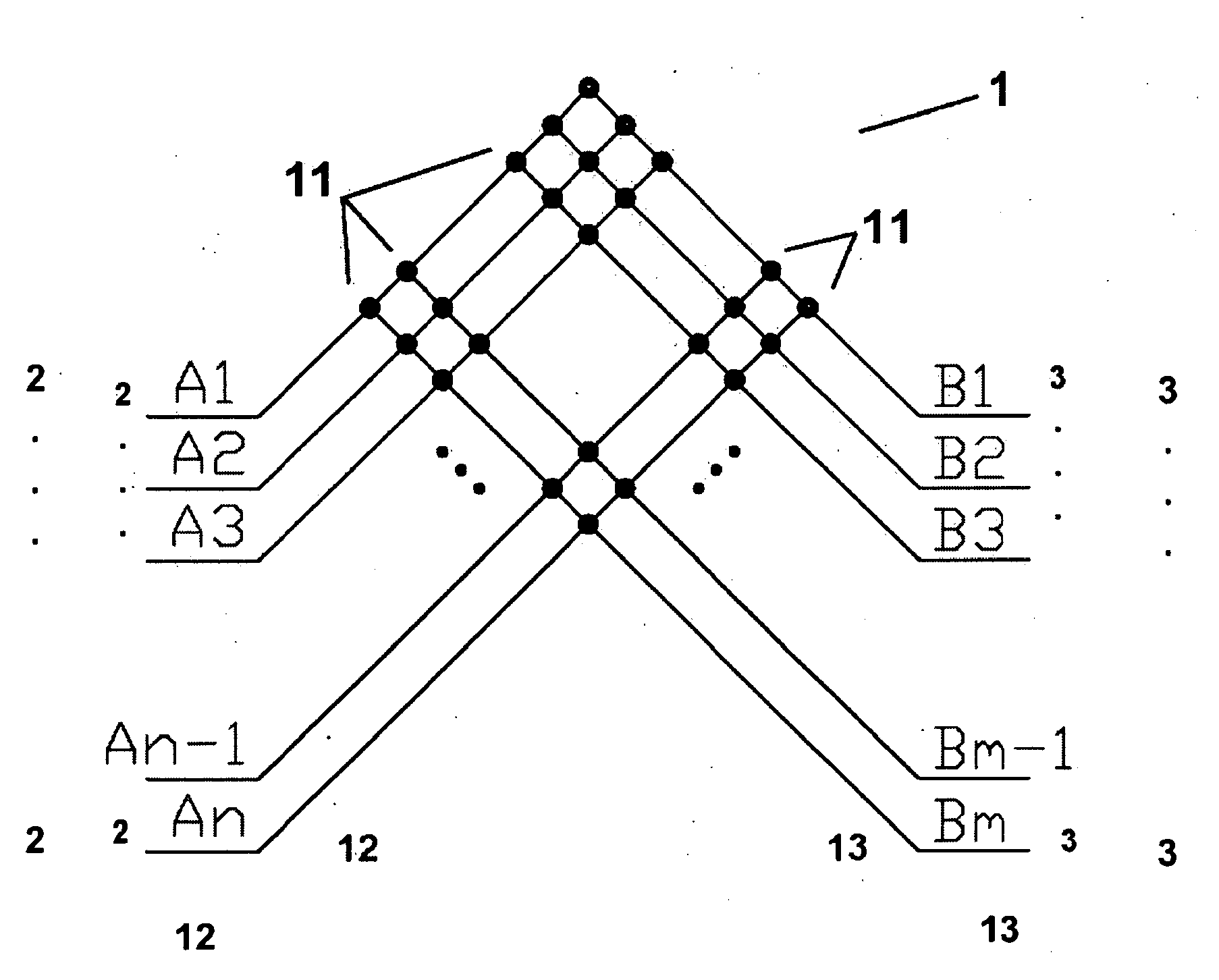
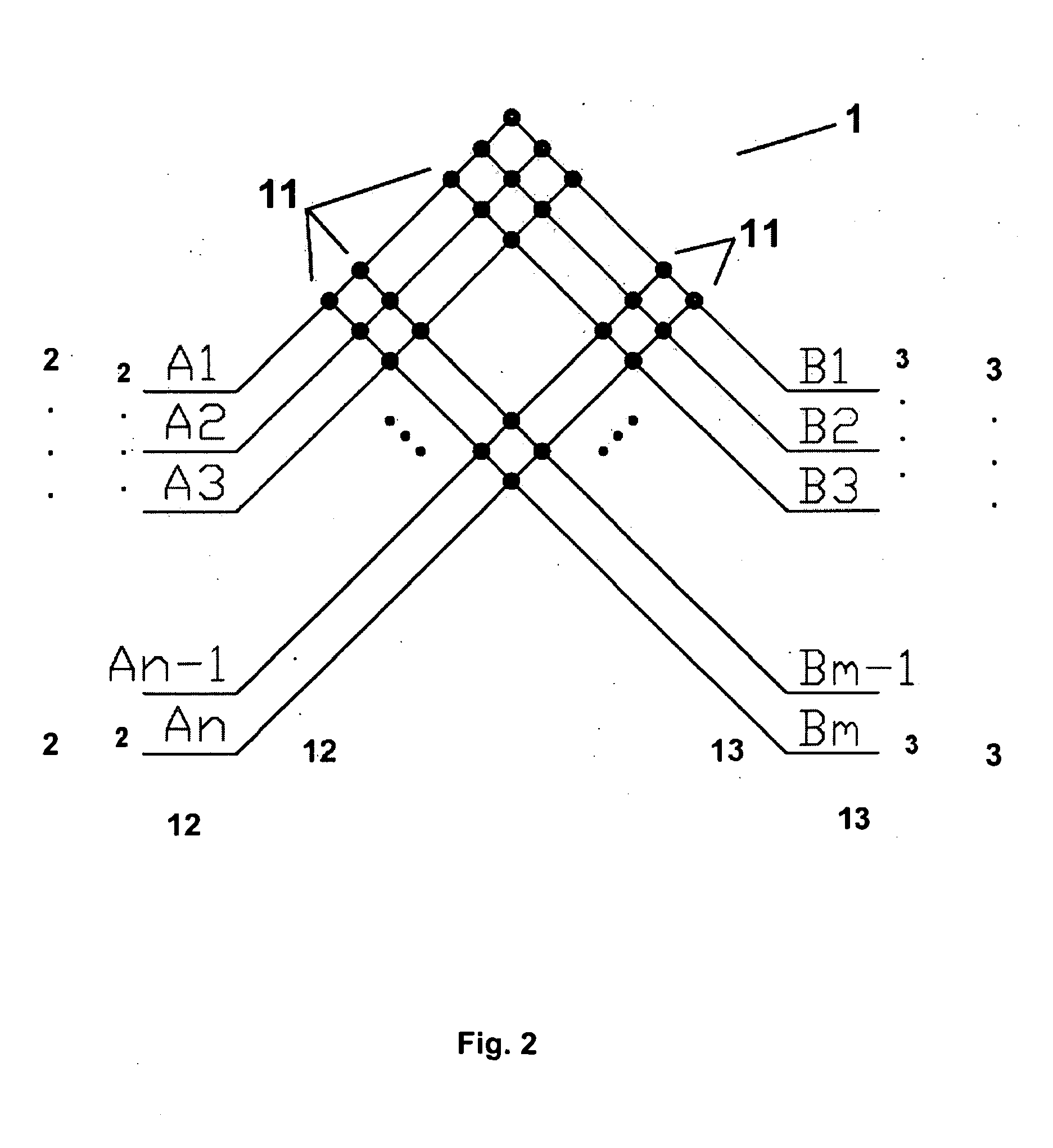
True arbitrary, any-to-any, non-blocking, fault tolerant, automated loop management systems that can support 100% fill in loop service for as many as forty thousand plus subscribers, as desired by the telephone industry, are either unavailable or largely prohibitively costly and unmanageable.
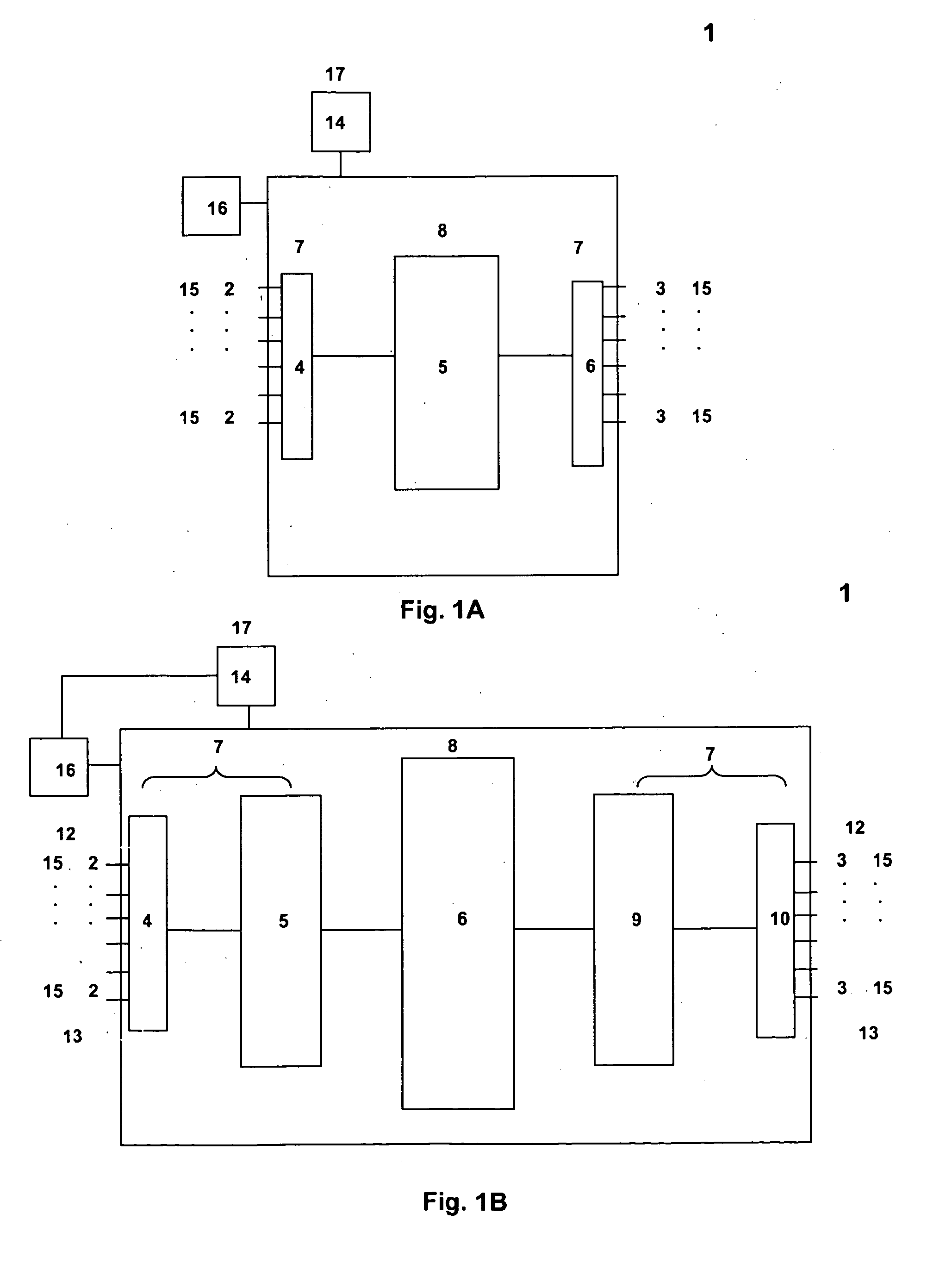
Matrix switches, such as devices that include an array of switches or cross-points arranged and interconnected where a node, a
signal or pair of lines, of an input set of nodes can be connected to a chosen node of an output set of output nodes such that a unique
signal path is created through the array can be difficult to work with.
Furthermore, composition of a large
one stage, any-to-any matrix switch (one of the most traditional designs) is often impractical because, as the number of input (perhaps considered feeder pairs in some applications) and output (perhaps considered distribution pairs in some applications) increases, the number of array elements grows exponentially.
A dominant cost factor in the construction of such fabrics may even be the number of cross-points in the fabric.
In
spite of this
impact, it remains a fact that this technique alone still does not provide enough reduction in array cross-point count to make the very large arrays desired by the telephone industry practical.
Following the recursive examples, however, it is a fact that application of successive levels of
recursion provides rapidly diminishing additional returns.
Unfortunately, because of the unanticipatable nature of the connections, there has been no known way to predict in advance which connection paths will not block the paths of future connections.
Breaking a connection to move it to another path to make room for a new connection also may be disruptive to subscriber services and therefore perhaps generally unacceptable.
For large arrays this doubles the size, complexity and cost of the
three stage system and the application of
recursion compounds the problem.
Thus, a switching fabric based on the
Clos Network desired by the telephone industry becomes much less feasible.
Applying additional levels of
recursion are unproductive as the cross-point count increases.
Thus a non-blocking array remains largely uneconomic.
As can be seen from the discussion so far, the problems of network switching fabric construction, its complexity and cost as faced by the telephone industry has been a significant impediment to “loop”
automation.
A drawback to even the present inventor's US
Patent Application 20040017805, to Smith, Robert B. disclosure, however, is that it does not overcome the conditionally non-blocking problem illustrated above.
As discussed above in our example, an array based on m=n is not strictly “non-blocking” and therefore cannot provide 100% fill without substantial service interruption during routing of new connections.
To some extent this group of disclosures focused on modifying the complexity and size of switching fabrics and / or control in novel, but not always in practical ways from the present perspective.
While this technique can reduce the number of blocked paths, it is not sufficient to provide a guarantee of 100% fill as would be required to utilize all input and outputs of the fabric, nor does it address the need for additional outer stage links around the inner stages for the recursive solution.
The addition of many mid stage links are required to prevent all potential blocking and therefore the method appears not very useful from the present perspective.
It does not adequately address the problem of ongoing service changes.
The scheme of U.S. Pat. No. 4,394,541 does not allow reassignment without disruption of other services, especially as the fabric nears 100% fill.
Unfortunately this folding wasted many cross-points in the resulting
square array.
In this case conserving unused inputs and outputs requires a considerable waste of cross-points.
In this manner the Clos method might appear not as useful as possible to reduce total cost or size.
In fact, total cost may go up because of the dominant influence of cross-points on overall cost.

