Apparatus for producing silicon

a technology of apparatus and silicon, applied in the direction of indirect heat exchangers, lighting and heating apparatus, silicon compounds, etc., can solve the problem of complex procedure and achieve the effect of increasing the degree of freedom

Active Publication Date: 2011-05-26
TOKUYAMA CORP
View PDF6 Cites 2 Cited by
  • Summary
  • Abstract
  • Description
  • Claims
  • Application Information

AI Technical Summary

Benefits of technology

In the apparatus for producing silicon of the present invention, the intermediate wall protruding toward the center side of the reaction vessel is formed between the reaction chamber and the recovery unit, and the reaction tube is supported by the intermediate wall. Namely, the reaction tube is placed stationary instead of being hanged down; i.e., stability is imparted to the structure that supports the reaction tube. The load exerted on the reaction is now the compressive force instead of the tensile force enabling the structure to become strong and permitting the reaction tube to be formed in a large size. In the apparatus for producing silicon, there is no need of feeding a sealing gas since the expansion member that expands and contracts in the up-and-down direction is air-tightly arranged between the upper end portion of the reaction tube and the ceiling portion of the reaction chamber.
In the apparatus for producing silicon, the structure for supporting the reaction tube has an increased degree of freedom since the support wall is formed on the upper surface of the intermediate wall and the reaction tube is supported by the support wall.
In the apparatus for producing silicon, the reaction tube comprises an outer cylindrical reaction tube and an inner cylindrical reaction tube arranged inside the inner circumferential surface of the outer cylindrical reaction tube maintaining a distance; a plurality of protruded portions are formed on the inner circumferential surface of the outer cylindrical reaction tube to protrude inwardly of the reaction vessel maintaining a distance in the circumferential direction of the inner circumferential surface; and the outer cylindrical reaction tube is supported by the intermediate wall while the inner cylindrical reaction tube is supported by the outer cylindrical reaction tube by utilizing the protruded portions. Thus, the inner cylindrical reaction tube of the double tubular structure, too, is supported in a stationary structure.
In the apparatus for producing silicon, the lower end portion of the reaction tube includes an annular flat portion formed on the outer circumferential side of the lower end portion of the reaction tube and a circular truncated conical portion of which the diameter decreases in a tapered manner from the inner circumferential side of the flat portion toward the lower side of the reaction tube in the radial direction thereof, and the flat portion is supported by the support wall so that the circular truncated conical portion protrudes inward beyond the support wall. Thus, the flat portion is supported by the partitioning wall maintaining stability, and the silicon is allowed to flow down from the lower end of the circular truncated conical portion without coming in contact with the partitioning wall.

Problems solved by technology

The Siemens' method has a feature in that it is capable of obtaining silicon of a high purity accompanied, however, by a problem in that since the precipitation is conducted batchwise, a very complex procedure must be conducted such as installing the silicon rod which plays a principal role, heating by flowing an electric current, precipitation, cooling, take out and washing the bell jar.

Method used


Image

  • Apparatus for producing silicon
  • Apparatus for producing silicon
  • Apparatus for producing silicon

Examples


first embodiment

An apparatus for producing silicon according to the invention will now be described with reference to the drawings.

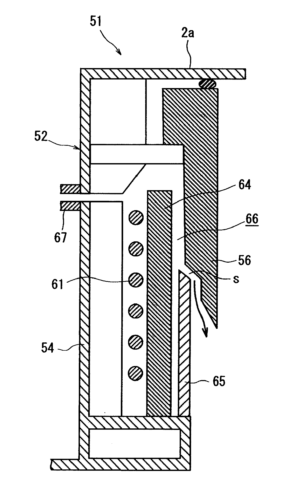
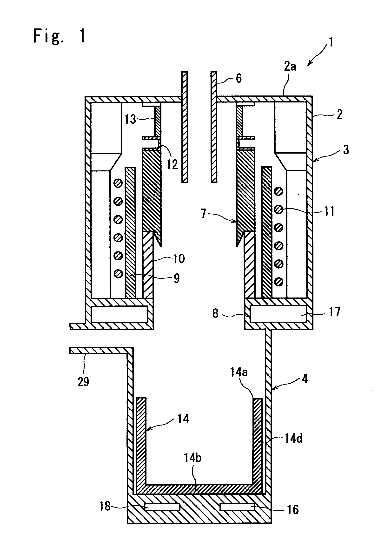
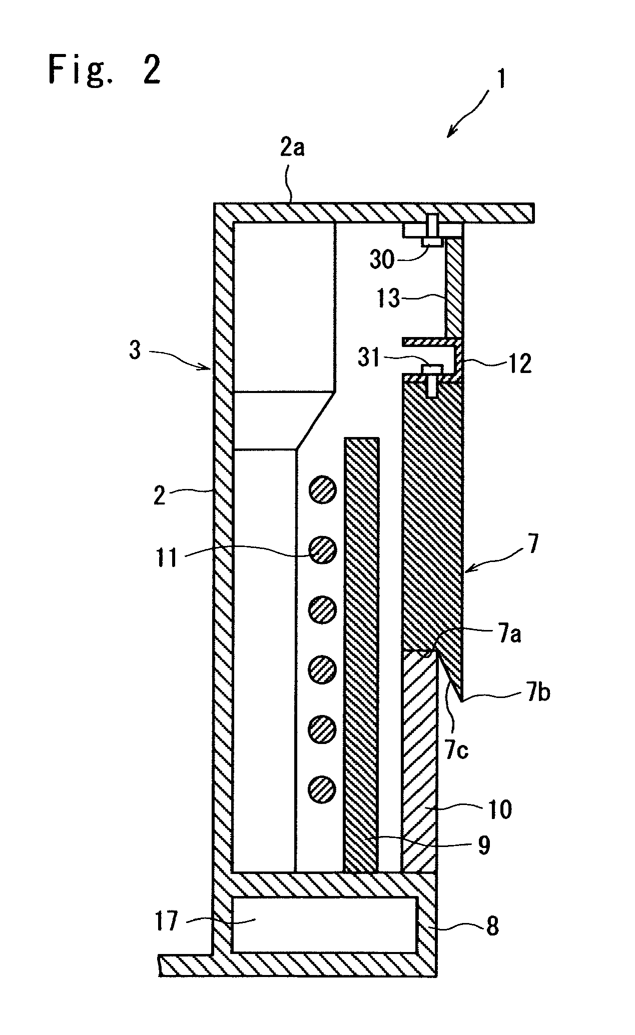
FIG. 1 illustrates an apparatus 1 for producing silicon according to the present invention. The apparatus 1 for producing silicon includes a reaction unit 3 that occupies the upper portion of a reaction vessel body 2 having a cylindrical outer wall and a recovery unit 4 that occupies the lower portion thereof. A cylindrical gas feed pipe 6 is provided in the central portion of a ceiling wall 2a of the reaction vessel body 2 to feed chlorosilanes and hydrogen that are the starting materials of silicon. The gas feed pipe 6 is so attached as to penetrate through the ceiling wall 2a with its axis being directed in the up-and-down direction. The gas feed pipe 6 is connected at its upper end side to gas feed means (not shown) that are capable of feeding chlorosilanes and hydrogen, respectively.

An annular intermediate wall 8 is provided between the reaction unit 3 and the reco...


PUM

PropertyMeasurementUnit
lengthaaaaaaaaaa
lengthaaaaaaaaaa
temperatureaaaaaaaaaa

Abstract

To provide a structure for mounting a novel reaction tube, which is capable of following up the thermal expansion of the reaction tube without the need of hanging down the reaction tube in the apparatus for producing silicon. In a reaction unit 3 in a reaction vessel body 2 of the apparatus 1 for producing silicon, there are provided a gas feed pipe 6 for feeding chlorosilanes and hydrogen, a reaction tube 7 for precipitating silicon, a high-frequency coil 11 arranged on the outer circumferential side of the reaction tube 7 to melt the precipitated silicon, a heat insulating material 9 provided between the reaction tube 7 and the high-frequency coil 11, and an intermediate wall 8 provided at the lower portion of the reaction unit 3 to support the heat insulating material 9. The reaction tube 7 is supported on the upper surface of the intermediate wall 8.

Description

TECHNICAL FIELDThis invention relates to an apparatus for producing silicon which is capable of stably supporting a reaction tube made of a material having a large coefficient of thermal expansion in a reaction vessel of silicon.BACKGROUND ARTIt has now been urged to efficiently produce polycrystalline silicon of a high purity accompanying the use of polycrystalline silicon in a variety of fields as a starting material of semiconductors and cells for solar generation that are expected to be further developed and demanded in the future.As a conventional method of producing polycrystalline silicon, there can be exemplified the Siemens' method according to which the surface of a silicon rod arranged, for example, in a bell jar is heated, and a starting gas for precipitating silicon containing chlorosilanes such as trichlorosilane (SiHCl3) or monosilane (SiH4) and a reducing gas such as hydrogen or the like is brought into contact with the surface of the silicon rod to precipitate the p...

Claims


Application Information

Patent Timeline
Patent Type & Authority Applications(United States)
IPC IPC(8): B01J19/00
CPCB01J19/24B01J2219/00141Y10T117/1024C01B33/029C01B33/03B01J2219/00148
Inventor NOUMI, HIROOWAKAMATSU, SATORUYOSHIMATSU, NOBUAKI
Owner TOKUYAMA CORP
Why Eureka
Try Eureka