Clot capture systems and associated methods

a technology of clot capture and capture system, which is applied in the field of devices and methods of removing acute obstructions from blood vessels, can solve the problems of ineffective clot removal, inability to navigate tortuous vessels, and large profile of conventional technology, etc., and achieve the effect of effective engagement and captur

Active Publication Date: 2011-05-26
NEURAVI
View PDF103 Cites 273 Cited by
  • Summary
  • Abstract
  • Description
  • Claims
  • Application Information

AI Technical Summary

Benefits of technology

[0007]The invention provides a clot retrieval device that can be delivered through a micro catheter. The device has sufficient structure to engage the clot. The device provides a means for debonding the clot from the vessel wall. The device further provides means to prevent the fragmentation of the clot and effectively retrieve the clot from the vessel.
[0170]In one embodiment the engagement element comprises an axial strut segment, a curved strut segment and a radial strut segment. With this embodiment the engagement element may be connected to a tubular member at the proximal end of the axial strut section. The struts of the axial segment may be oriented substantially parallel to the axis of the clot debonding device. The engagement element may comprise an immediate segment distal of the axial segment. The intermediate segment may comprise the radial curve. The intermediate section may comprise most of the engagement surface. The intermediate section may provide a high area surface for the transmission of force to the clot.

Problems solved by technology

Acute obstructions may include clot, misplaced devices, migrated devices, large emboli and the like.
Accessing the neurovascular bed is difficult with conventional technology as the target vessels are small in diameter, are remote relative to the site of insertion and are highly tortuous.
The reasons for this are that conventional technology is either too large in profile, lacks the deliverability to navigate tortuous vessels or is not effective at removing clot when delivered to the target site.

Method used


Image

  • Clot capture systems and associated methods
  • Clot capture systems and associated methods
  • Clot capture systems and associated methods

Examples


Embodiment Construction

[0447]The present invention is related to an apparatus and methods for the removal of obstructions in vessels. More particularly the present invention relates to devices and methods for the removal of obstructive clot from cerebral vessels.

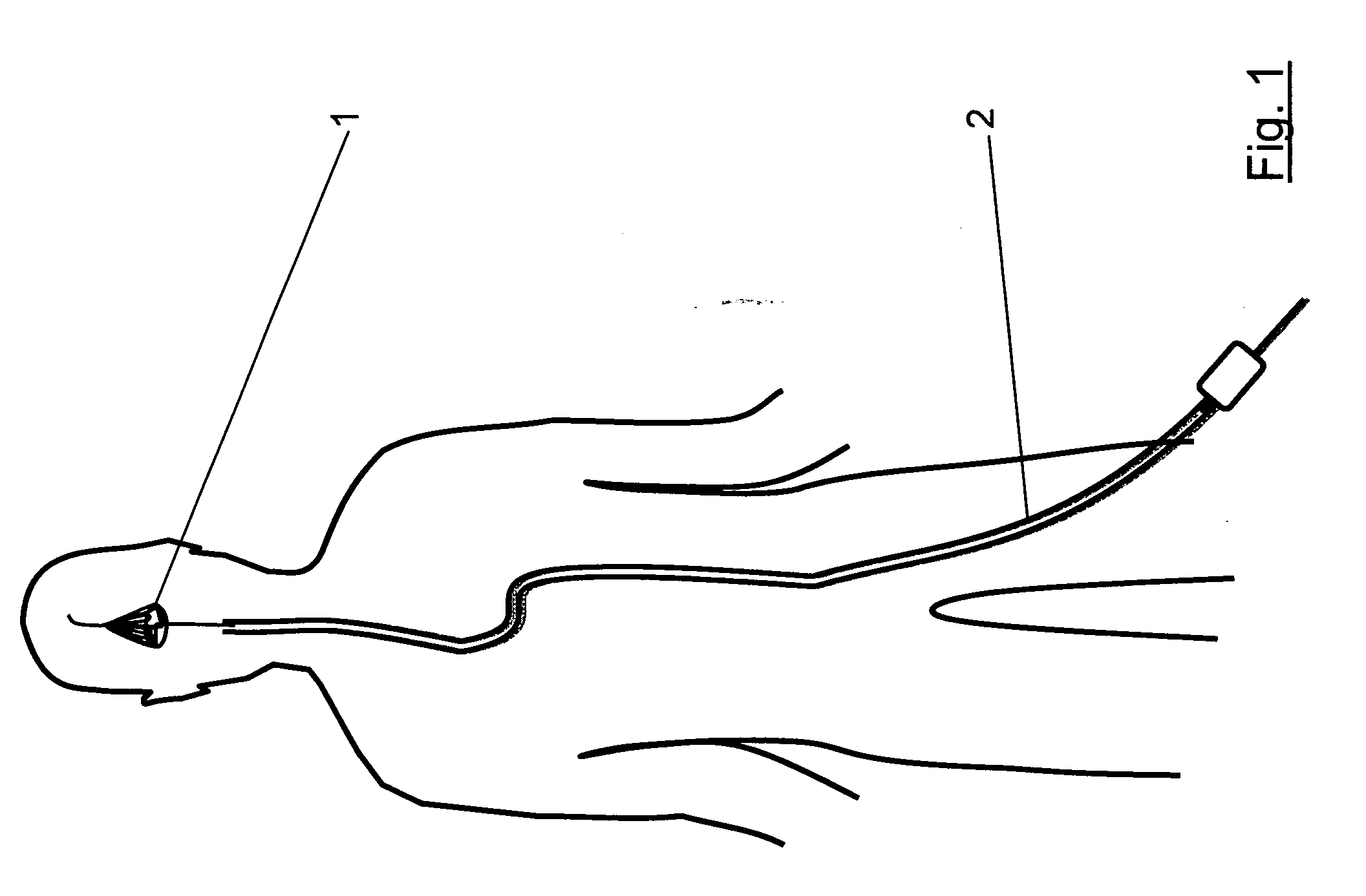
[0448]With reference to FIG. 1 there is shown a schematic representation of the catheterization of a patient with a clot retrieval device 1 according to the invention. The patient is catheterized via the femoral artery with a catheter 2 in accordance with standard interventional technique.

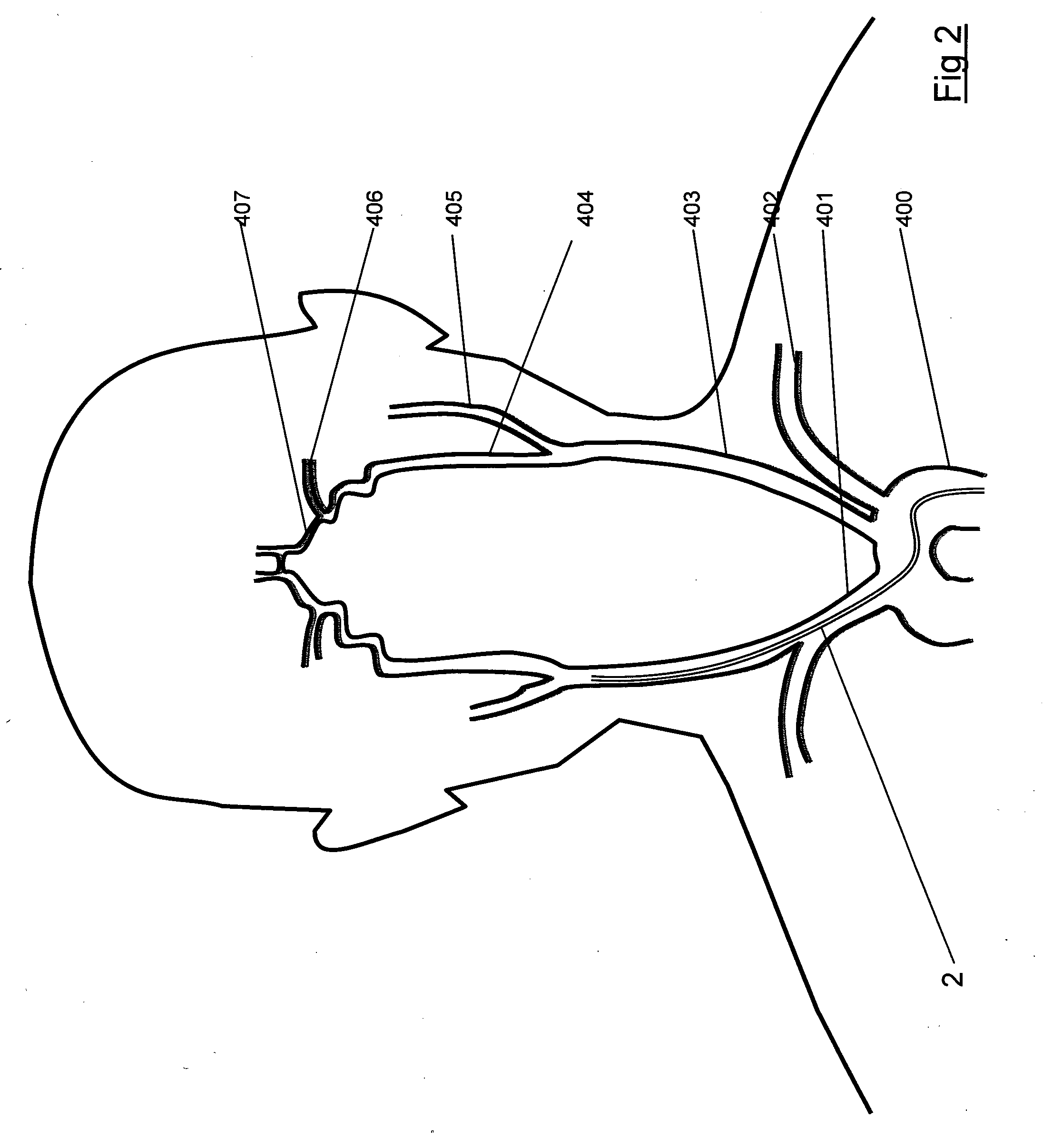
[0449]FIG. 2 shows a schematic representation of some of the arteries supplying blood to the brain. The arteries shown are on the anterior circulation. Vessel 400 is the Aorta. Vessel 401 is the brachiocephalic artery. Vessel 402 is the subclavian artery. Vessel 403 is the common carotid artery. Vessel 404 is the internal carotid artery. Vessel 405 is the external carotid artery. Vessel 406 is the middle cerebral artery. Vessel 407 is the anterio-cerebral artery....


PUM


Abstract

A clot capture system for disengaging a clot 2001 from a vessel wall 2002 and removing the clot 2001 from the vessel 202, comprises a clot capture device 2140 for placement on a distal side of a clot 2001. The clot capture device 2140 has a retracted delivery configuration and an expanded deployed configuration. The clot removal device has a proximal support frame 2012, and a distal fibre net 2130. The support frame 2012 has a retracted delivery configuration and an expanded deployed configuration. The proximal support frame 2012 in the expanded configuration defines a proximal inlet mouth for engaging a clot 2001 and a net 2130 for confining the clot 2001. An elongate member facilitates capture and / or withdrawal of a clot 2001 from a vessel 2002. The system also comprises a clot debonding device 2091 for placement on a proximal side of a clot 2001. The clot debonding device 2091 has a retracted delivery configuration and an expanded deployed configuration and comprises a clot engagement element 2112 which defines a distal abutment in the deployed configuration for urging a clot 2001 into the clot cap 2140.

Description

[0001]This is a national stage of PCT / IE09 / 000051 filed Jul. 22, 2009 and published in English, claiming benefit of U.S. provisional application No. 61 / 129,823, filed Jul. 22, 2008, and claiming benefit of U.S. provisional application No. 61 / 202,612, filed Mar. 18, 2009, hereby incorporated by reference.INTRODUCTION[0002]The invention relates to devices, and methods of removing acute blockages from blood vessels. The invention especially relates to removing acute obstructions from blood vessels. Acute obstructions may include clot, misplaced devices, migrated devices, large emboli and the like. More particularly the invention relates to removing clot from cerebral arteries in patients suffering acute ischemic stroke.[0003]Accessing the neurovascular bed is difficult with conventional technology as the target vessels are small in diameter, are remote relative to the site of insertion and are highly tortuous. Despite the fact that there are over 600,000 acute ischemic strokes in the U...

Claims


Application Information

Patent Timeline
Patent Type & Authority Applications(United States)
IPC IPC(8): A61F2/01
CPCA61B17/221A61F2230/0058A61B2017/00867A61B2017/2212A61B2017/22038A61B2017/2217A61B2017/22035A61B17/22031A61F2230/005A61F2/01A61B2017/2215A61B2017/22051A61F2230/001A61B2017/22094A61F2230/0008
Inventor BRADY, EAMONRAZAVI, MAHMOODVALE, DAVIDO'SHAUGHNESSY, JOHN
Owner NEURAVI
Why Eureka
Try Eureka