Regenerator for syngas cleanup and energy recovery in gasifier systems

a gasifier and energy recovery technology, applied in the direction of molten salt/metal gasification, combustion types, sustainable manufacturing/processing, etc., can solve the problems of increasing environmental problems, increasing the number of waste generation, and increasing the difficulty of gasification, so as to reduce the amount of syngas and reduce the heating requirement

Active Publication Date: 2011-06-02
INENTEC
View PDF44 Cites 12 Cited by
  • Summary
  • Abstract
  • Description
  • Claims
  • Application Information

AI Technical Summary

Benefits of technology

[0011]The problems of the prior art are overcome by the apparatus and method disclosed herein. A rotating or otherwise moving material is used to recover heat from the syngas at it exits the reactor vessel. In some embodiments, three or more streams are passed through the heat exchanger. One stream is the dirty syngas, which heats the rotating material. A second stream is a cold stream which is heated as it passes through the material. A third stream is a cleaning stream, which serves to remove particulates and other deposits that condense on the regenerator material that are collected on the rotating material as the dirty syngas passes through it. This apparatus can also be used as an auto-regenerator (that is, the same material flows through the hot and then cold section of the regenerator), or it can exchange heat between separate flows in the gasifier process. The apparatus can also be used to reduce the heating requirement for the thermal residence chamber (TRC) used downstream from the gasification system, and thereby reduce the amount of syngas that must be oxidized and the amount of oxygen that must be provides in order to heat the TRC.

Problems solved by technology

The generation of waste, particularly solid waste has become an increasingly worrisome environmental issue.
In addition, much of today's solid waste is not readily biodegradable, implying that the waste will not decompose in a timely manner.
However, these incinerators burn the waste and generate air pollutants which require very extensive gas cleanup, create ash which can be hazardous and produce energy only in the form of heat which is converted into electricity.
Despite the advantages of plasma gasifiers, one issue associated with the use of plasma gasifiers is the amount of energy used to raise the temperature of feedstocks, the syngas and the slag.
This heat is then lost when the syngas is cooled as it is being cleaned.
However, the use of heat exchangers (also known as regenerators) in waste and biomass gasification systems has been inhibited by the harsh environment in which they must operate.
First, the syngas, at the point it passes through the heat exchanger, is not clean.
Once tars and other particulates collect on the heat exchanger, the flow of gas through the exchanger is compromised, thereby impacting the utility of the device.
The honeycomb structures which have been considered for recuperation in other applications do not have sufficiently small microhole structures to capture the particulate matter.
In addition, the syngas at this point is at extremely high temperatures, making the selection of a suitable material for a heat exchanger difficult.
This often means that the heat exchanger media has to move or rotate to affect this reversal of streams.
Movement and sealing of moving parts at high temperatures is often problematic.

Method used


Image

  • Regenerator for syngas cleanup and energy recovery in gasifier systems
  • Regenerator for syngas cleanup and energy recovery in gasifier systems
  • Regenerator for syngas cleanup and energy recovery in gasifier systems

Examples


Embodiment Construction

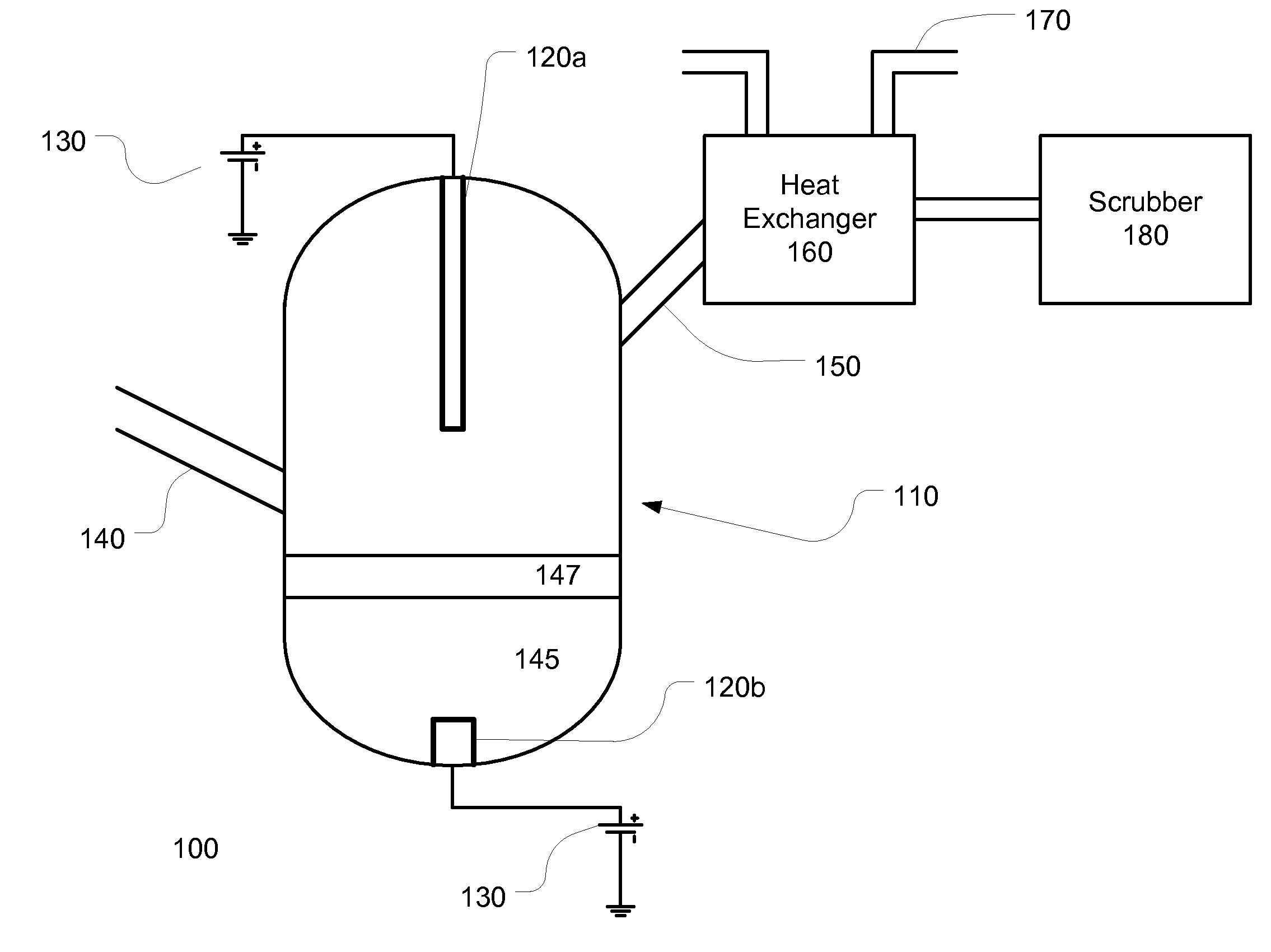
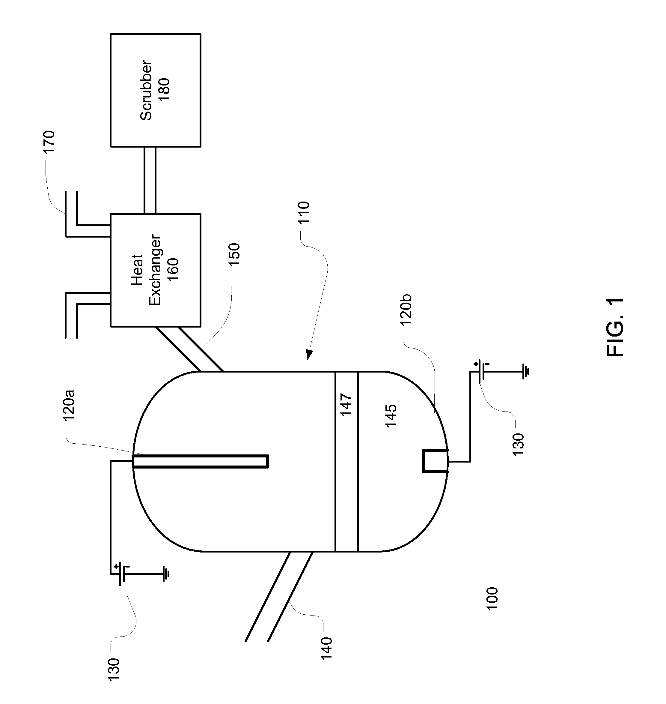
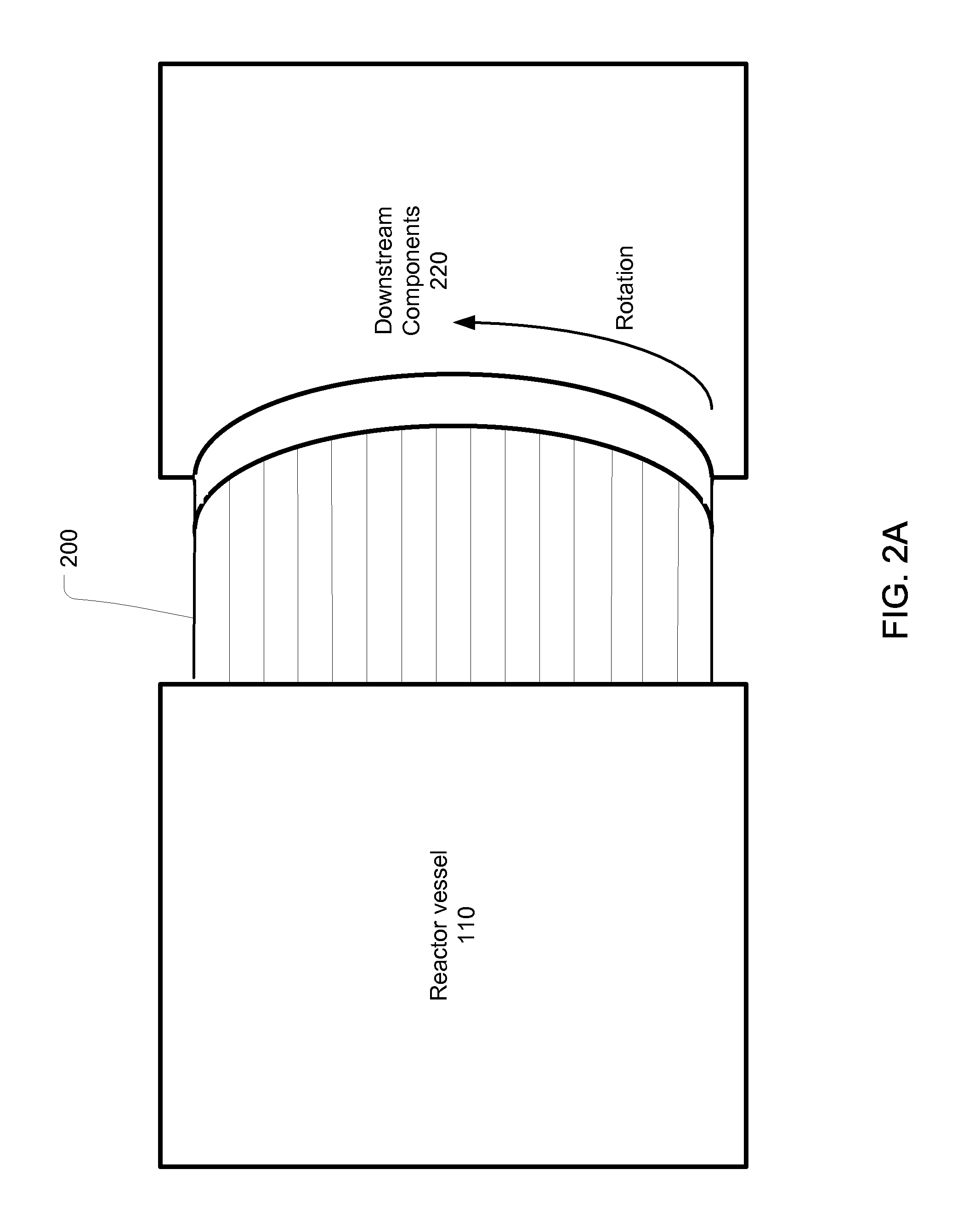
[0024]FIG. 2A shows a schematic diagram of a rotating energy exchanger 200. The energy exchanger 200 may be located between the vessel 110 and other downstream components 220. FIG. 2B shows a representative cross sectional view of an energy exchanger 300. The heated stream passes through a portion 310 of the energy exchanger, while a cold stream is passed through a second portion 320. The line 315 between the two portions signifies a wall or other separator that keeps the two flows apart. The heated stream imparts its thermal energy to the first portion 310 of the energy exchanger 300. The energy exchanger 300 is rotated, such that the recently heated portion of the energy exchanger 300 is not used by the heated stream. Instead, the cold stream flows through the heated portion of the energy exchanger, where the energy flows from the thermal mass of the energy exchanger 300 to the cold stream. The net effect is that the heated portion 310 releases its stored heat to the cold stream. ...


PUM

PropertyMeasurementUnit
temperatureaaaaaaaaaa
pressureaaaaaaaaaa

Abstract

A rotating heat regenerator is used to recover heat from the syngas at it exits the reactor vessel of a waste or biomass gasifier. In some embodiments, three or more streams are passed through the heat exchanger. One stream is the dirty syngas, which heats the rotating material. A second stream is a cold stream that is heated as it passes through the material. A third stream is a cleaning stream, which serves to remove particulates that are collected on the rotating material as the dirty syngas passes through it. This apparatus can also be used as an auto-heat exchanger, or it can exchange heat between separate flows in the gasifier process. The apparatus can also be used to reduce the heating requirement for the thermal residence chamber (TRC) used downstream from the gasification system.

Description

[0001]This application claims priority of U.S. Provisional Patent Application 61 / 181,099, filed May 26, 2009, the disclosure of which is incorporated herein by reference.BACKGROUND[0002]The generation of waste, particularly solid waste has become an increasingly worrisome environmental issue. Many landfills are becoming filled to the point where additional waste cannot be deposited therein. In addition, much of today's solid waste is not readily biodegradable, implying that the waste will not decompose in a timely manner. As an alternative, incinerators have been employed to burn solid waste, so as to minimize its physical footprint. However, these incinerators burn the waste and generate air pollutants which require very extensive gas cleanup, create ash which can be hazardous and produce energy only in the form of heat which is converted into electricity.[0003]Plasma gasifiers offer an alternative to these current approaches. Plasma gasifiers use intense electrically based heating...

Claims


Application Information

Patent Timeline
Patent Type & Authority Applications(United States)
IPC IPC(8): C10J3/72F23L15/02F16J15/16
CPCC10J3/18C10J3/57C10J3/84C10J2200/09C10J2200/12C10J2300/1238F28D19/02F23G5/085Y02E20/12C10J3/78C10J3/86F16J15/16C10J2300/1884Y02P20/10B01J7/00B01J19/081B01J2219/0879B01J2219/0898C01B3/02C10J3/82F16J15/46
Inventor BROMBERG, LESLIECOHN, DANIEL R.SURMA, JEFFREY E.BATDORF, JAMES A.LAMAR, DAVID A.
Owner INENTEC
Why Eureka
Try Eureka