Exhaust turbine equipped with exhaust control valve

a technology of exhaust gas control valve and exhaust gas turbine, which is applied in the direction of valve operating means/release devices, machines/engines, mechanical equipment, etc., can solve the problems of not firmly maintaining the valve body at an expected location, reduce the vibration level of the exhaust gas control valve, reduce the number of components and assembly costs, and reduce the effect of effective results

Active Publication Date: 2011-06-02
MITSUBISHI HEAVY IND ENGINE & TURBOCHARGER LTD
View PDF2 Cites 23 Cited by
  • Summary
  • Abstract
  • Description
  • Claims
  • Application Information

AI Technical Summary

Benefits of technology

[0033]Therefore, the inertia mass (the moment of inertia) around the axis 8 as to the running gear parts of the waste gate valve is increased due to the provided weight, in contrast to the conventional way; thus the swing vibration of the valve body around the axis of the support axis shaft due to the pressure pulsation in the exhaust gas emitted from the engine can be restrained.
[0034]Moreover, due to the increased moment of inertia as to the moving parts of the exhaust gas control valve thereby the increased moment of inertia is attributable to the provided weight that is equipped at the end part counter to the connecting part via which the moving parts of the exhaust gas control valve are operated as per the movements of drive source, the angular velocity change as to the swing movement of the arm and the support axis shaft in response to the engine exhaust gas pressure pulsation can be smooth; thus, the relative movement between the bush (or a hole in the turbine casing to place the support axis shaft) and the support axis shaft connected to the valve body can be also smooth. In this way, the vibration levels of the exhaust gas control valve can be reduced over the whole operation zone of the valve body (, besides, in the middle operation zone of the valve body or under the closed condition thereof).
[0035]Further, in this embodiment, the center of the exhaust gas control valve (namely, the center of the valve body) is located at a predetermined distance S from the connecting part via which moving parts of the exhaust gas control valve are operated as per the movements of drive source, in the direction of the axis of the sup

Problems solved by technology

As a matter of fact, in the conventional technology of the patent reference 1 (JP1995-10434), the valve body of the waste gate valve is firmly pressed and maintained to a p

Method used


Image

  • Exhaust turbine equipped with exhaust control valve
  • Exhaust turbine equipped with exhaust control valve
  • Exhaust turbine equipped with exhaust control valve

Examples


first embodiment

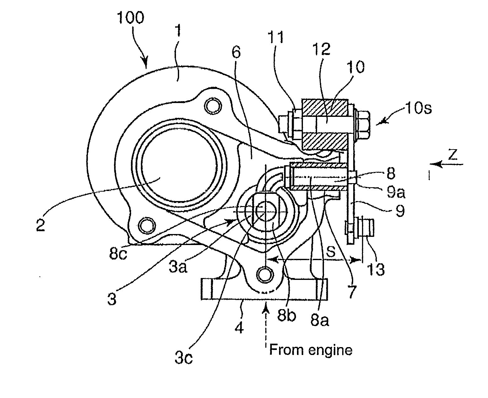
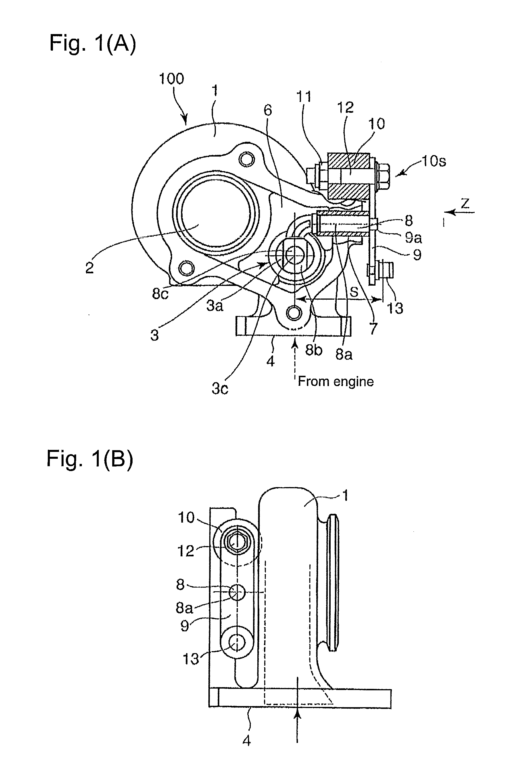
[0044]FIG. 1(A) shows the structure of the waste gate valve (the exhaust gas flow rate control valve) as well as the structure around the waste gate valve in the exhaust gas turbine of the exhaust gas turbocharger, according to the first embodiment of the present invention; FIG. 1(B) shows a view as to the Z-arrow in FIG. 1(A).

[0045]The exhaust gas turbine 100 shown in FIGS. 1(A) and 1(B) comprises a turbine casing 1 in which a turbine 2 (details not shown) is provided with a waste gate valve 3. The waste gate valve 3, as shown in FIG. 3(A) and FIG. 3(B), is for diverging the exhaust gas emitted from the engine (not shown) to the turbine 2 via an exhaust gas passage 6, in the exhaust gas passage 6 located upstream of the turbine 2 so that the diverged exhaust gas bypasses the turbine 2 and flows to an exhaust gas outlet passage 5a via an exhaust gas bypass passage 5. In addition, the numeral 4 denotes an exhaust gas inlet flange.

[0046]As is the case with FIGS. 3(A) and 3(B), a valve...

second embodiment

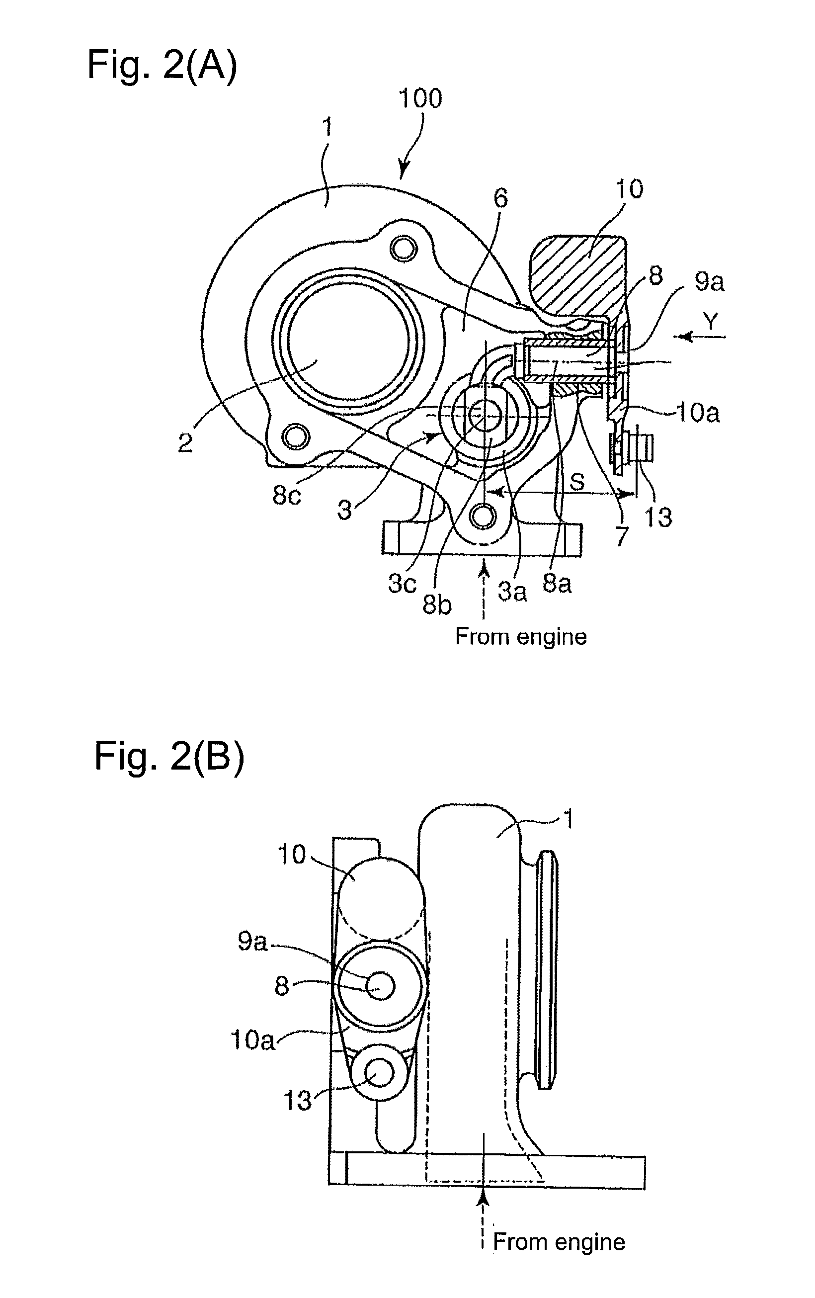
[0058]FIG. 2(A) shows the structure of the waste gate valve (the exhaust gas flow rate control valve) as well as the structure around the waste gate valve in the exhaust gas turbine of the exhaust gas turbocharger, according to the second embodiment of the present invention; FIG. 2(B) shows a view as to the Y-arrow in FIG. 1(A).

[0059]In this second embodiment as shown in FIG. 2(A), the arm 10a and the weight 10 are formed as a single-piece construction made by casting or forging. The middle part of the arm 10a is fitted to the support axis (shaft)) 8 by means of the caulking device 9a. Other configuration or component arrangement is the same as that of the first embodiment; the common symbols or numerals are used for the common components in the first and the second embodiments

[0060]The second embodiment brings effective results, as is the case with the first embodiment. In addition, since the arm 10a and the weight 10 are formed as a single-piece construction made by casting or for...


PUM


Abstract

Provided is an exhaust turbine equipped with an exhaust control valve (waste gate valve) which can reduce wear of the contact surfaces between the shaft and the bushing or the turbine casing that support the moving components of the valve in the entire operating range of the exhaust control valve. The exhaust turbine is equipped with the exhaust control valve for opening/closing an exhaust bypass passage which extends from an exhaust passage leading the exhaust turbine being driven by exhaust gas output from an engine to an exhaust outlet passage while bypassing the exhaust turbine, wherein the exhaust control valve comprises a shaft which is supported rotation-freely by a bushing or a turbine casing and supports a valve element for controlling the opening of the exhaust bypass passage, an arm equipped with a connecting part with a drive source and turning the shaft about the axis thereof by the reciprocating motion of the connecting part produced by the drive source, and a weight attached to an end on the side opposite to the connecting part with the drive source with respect to the axis of the shaft.

Description

BACKGROUND OF THE INVENTION[0001]1. Field of the Invention[0002]The present invention relates to an exhaust gas turbine that is driven by exhaust gas emitted from an engine, more specifically, the present invention relates to an exhaust gas turbine equipped with an exhaust gas control valve, i.e. a waste gate valve, for closing and opening an exhaust gas bypass passage so that the exhaust gas emitted from an engine bypasses the exhaust gas turbine and flows into an exhaust gas outlet passage.[0003]2. Background of the Invention[0004]In an exhaust gas turbocharger of a relatively smaller size class, the exhaust gas turbine therein that is driven by the exhaust gas emitted from the engine is provided with a waste gate valve for closing and opening the exhaust gas bypass passage through which the exhaust gas emitted from the engine toward the exhaust gas turbine bypasses the exhaust gas turbine and flows into an exhaust gas (waste gas) outlet passage; in a case where the flow rate of t...

Claims


Application Information

Patent Timeline
IPC IPC(8): F02G5/00
CPCF01D17/105F02B37/183F02B37/186F05D2230/21Y02T10/144F05D2220/40F02C6/12Y02T10/12
Inventor YOSHIMOTO, TAKASHIJINNAI, YASUAKITOJO, MASAKIHAYASHI, NORIYUKI
Owner MITSUBISHI HEAVY IND ENGINE & TURBOCHARGER LTD
Why Eureka
Try Eureka