Supercharge Your Innovation With Domain-Expert AI Agents!

Visualization Instrument

a technology of visualization and instruments, applied in the field of visualization instruments, can solve the problems of insufficient lighting to produce a good optical image, inability to project images remotely, and inability to achieve good optical imag

Active Publication Date: 2011-06-02
KING SYST
View PDF103 Cites 59 Cited by
  • Summary
  • Abstract
  • Description
  • Claims
  • Application Information

AI Technical Summary

Benefits of technology

[0007]In one example thereof, the insertable portion further comprises a guide pathway adapted for guiding a tube into a patient, the distal cavity and the guide pathway arranged laterally to each other to reduce an anterior / posterior height of the insertable portion.
[0010]In a further example, the insertable portion further comprises an anterior wall and a medial wall, the anterior wall and the medial wall defining a guide pathway adapted for guiding a tube into a patient, the guide pathway adjacent a side of the medial wall and the distal cavity adjacent an opposite side of the medial wall, the anterior wall having a tip portion extending distally beyond the medial wall. In a variation thereof, the tip portion includes a textured surface adapted to engage a tissue of the patient. In another variation thereof, the textured surface includes a plurality of ridges arranged in a regulated pattern. In a further variation thereof, the plurality of ridges are longitudinally aligned. In yet another variation thereof, the textured surface has a first coefficient of friction measured in a first direction and a second coefficient of friction measured in a second direction different from the first direction. In a further variation thereof, the tip portion includes one or more flexural support feature. In another variation thereof, the one or more flexural support feature increases a flexural strength of the tip portion by at least 5%. In another variation thereof, the flexural support feature comprises at least one of a longitudinally aligned ridge, a longitudinally aligned wall portion, and a transverse curvature of the tip portion.
[0041]In yet another exemplary embodiment of the present disclosure, a visualization instrument is provided. The visualization instrument comprising a display device including a display driver and a display; an imaging assembly having an image sensor, a transparent cover, a lens between the image sensor and the transparent cover, and an illumination device illuminating a cavity of the patient, the imaging assembly configured to transfer an image stream representing views of the cavity to the display device; a control component including a processor, a memory, and a program embedded in the memory, the processor receiving the data stream from the imaging assembly, transforming the data stream into a second data stream, and providing the second data stream to the display driver to show the views of the cavity on the display; a housing coupled to the display device and having a first connector configured to receive the second data stream from the control component; and an insertable portion having a proximal cavity configured to receive the housing and a distal end having a distal cavity configured to receive the imaging assembly, the insertable portion also including a second connector, a passageway, and a distal tip, the second connector configured to transfer the first image stream from the imaging assembly through the first connector to the control component, passageway configured to guide insertion of an elongate tubular component into the cavity, and the distal tip engaging a glottis of a patient, the distal tip having a lateral wall extending distally beyond the distal cavity and a textured surface configured to engage the glottis, wherein the distal tip exhibits a curvature perpendicularly to a length of the insertable portion and includes at least a portion of a ridge parallel to the length of the insertable portion, the curvature and the ridge enhancing the flexural strength of the distal tip by at least 5%.

Problems solved by technology

Each instrument has its own limitations such as, for example, fogging, insufficient lighting to produce a good optical image, inability to project images remotely, additional procedural steps to insert the endotracheal tube, and cost.

Method used


Image

  • Visualization Instrument
  • Visualization Instrument
  • Visualization Instrument

Examples


Embodiment Construction

[0072]The embodiments of the disclosure discussed below are not intended to be exhaustive or limit the invention to the precise forms disclosed in the following detailed description. Rather, the embodiments are chosen and described so that others skilled in the art may utilize their teachings.

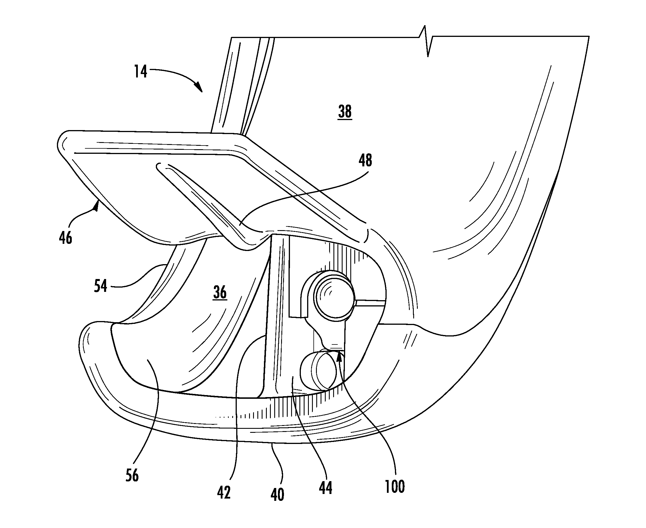
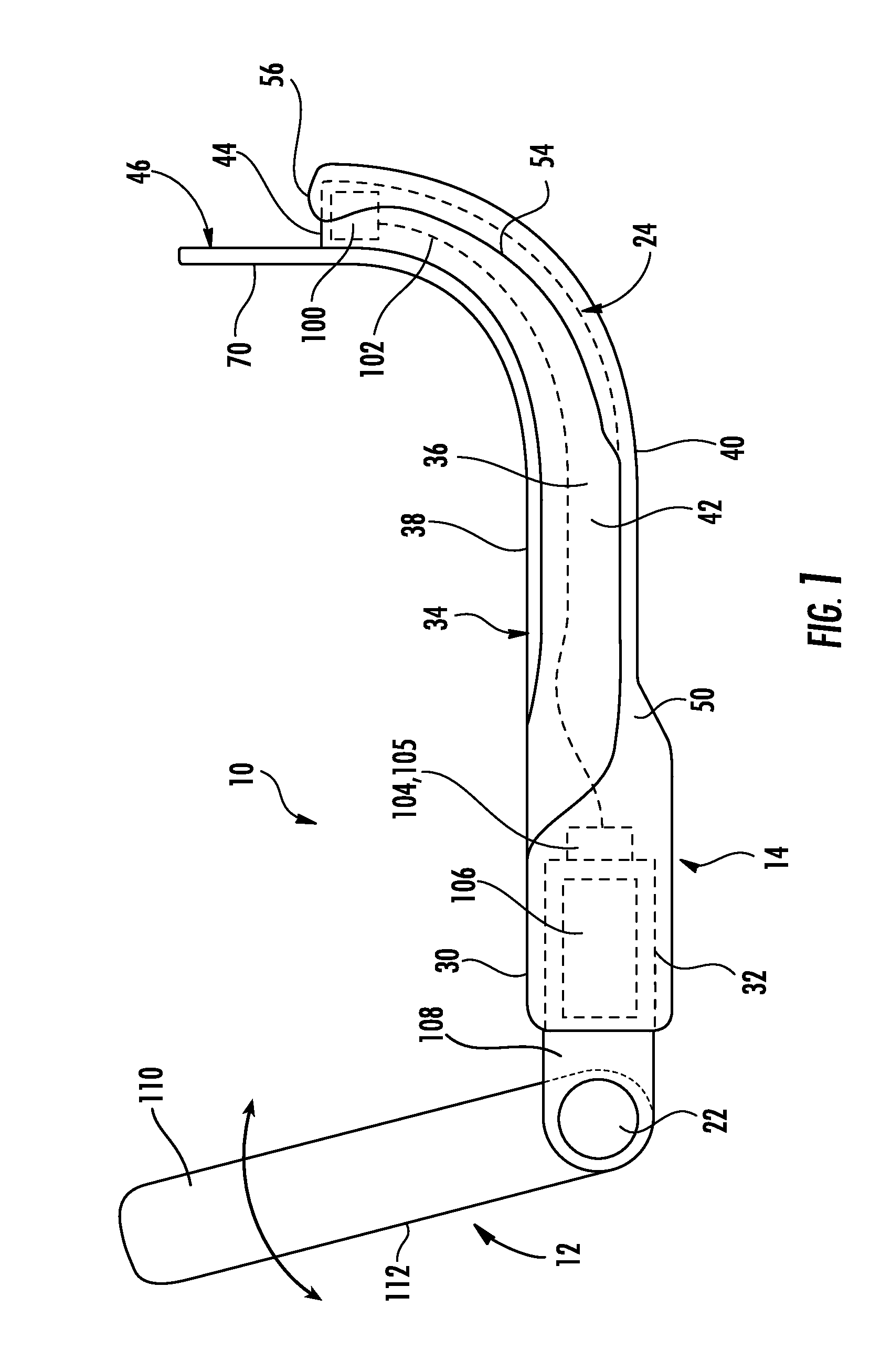
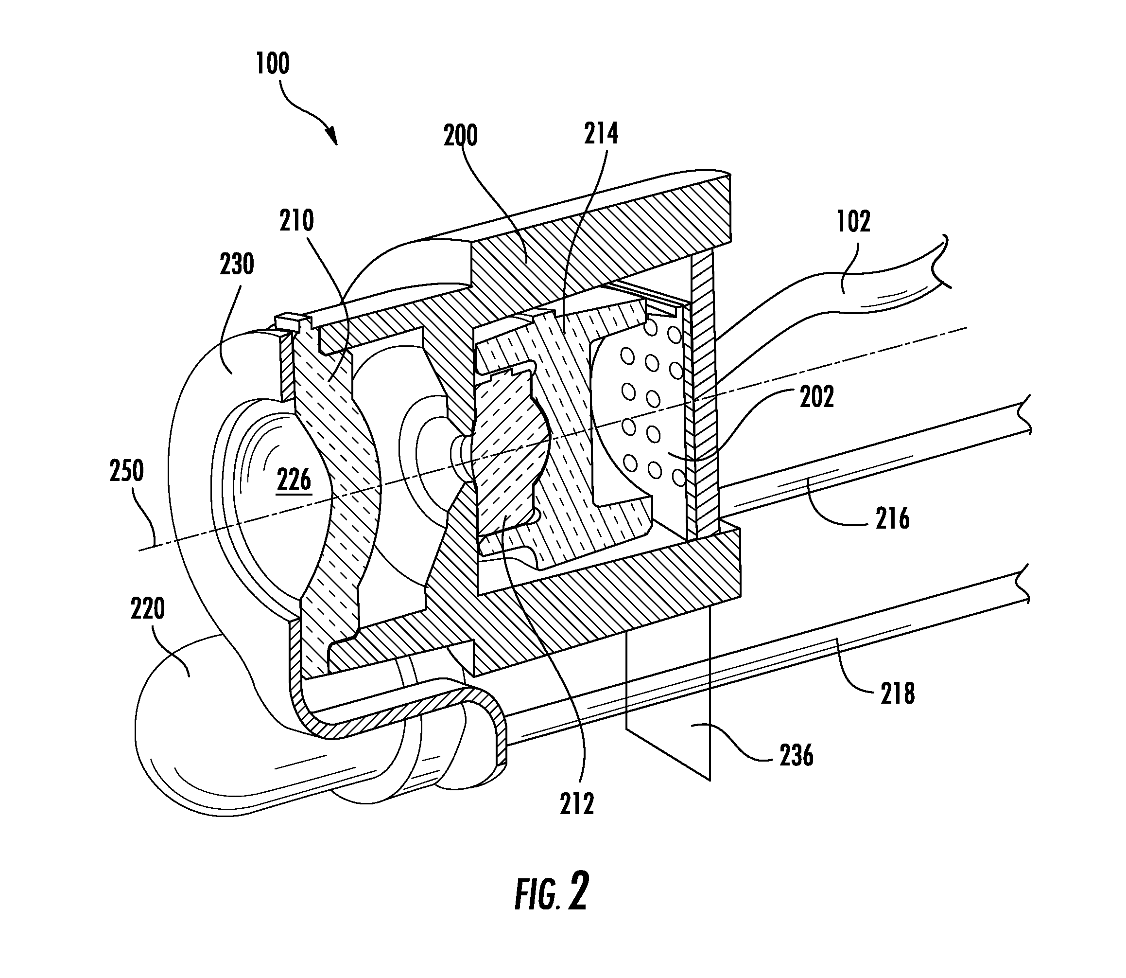
[0073]A visualization instrument, and a method of using the instrument, are disclosed herein. In one embodiment of the visualization instrument, the visualization instrument comprises a display screen and a display screen support portion removably and electrically coupled to an insertable portion including an imaging system to acquire images of an internal space. Exemplary visualization instruments include endoscopes, laryngoscopes, and stylets. The display screen support portion and the display screen may be integrally constructed and may be reusable or disposable. In various embodiments described below, a unitary component comprising the display screen and the display screen support portion i...


PUM


Abstract

A visualization instrument comprising a display support component removably coupled to a component insertable into a target space. The insertable component includes a camera providing images of the target space. The images are presented in a display device supported by the display support component. The insertable component may be discarded after a permitted number of uses.

Description

CROSS-REFERENCE TO RELATED APPLICATIONS[0001]This application claims the benefit of priority from U.S. patent application Ser. No. 61 / 314,058 entitled INTUBATION INSTRUMENT WITH VISUALIZATION FEATURES filed on Mar. 15, 2010 and U.S. Patent Application Ser. No. 61 / 265,330 entitled INTUBATION SYSTEM WITH ELASTOMERIC FEATURES filed on Nov. 30, 2009, the disclosures of which are expressly incorporated by reference herein in their entirety.FIELD OF THE DISCLOSURE[0002]The present disclosure relates generally to a system including a visualization instrument comprising a camera to view an internal space and, more particularly, to a visualization instrument comprising a camera to examine the interior of a patient.BACKGROUND[0003]Visualization instruments include endoscopes, laryngoscopes, borescopes and other medical instruments designed to look inside the body of a patient. Medical visualization instruments are used in a multitude of medical procedures including laryngoscopy, rhinoscopy, b...

Claims


Application Information

Patent Timeline
IPC IPC(8): A61B1/267
CPCA61B1/00016A61B1/00052A61B1/00103A61B1/00105G02B23/2446A61B1/05A61B1/267G02B23/2423A61B1/018A61B1/04A61B1/01
Inventor MCGRAIL, THOMAS W.PARGETT, MICHAEL S.MILLER, DAVID J.YEH, YUN SIUNG TONYCHINNOCK, RANDAL B.GRUBNER, GEORGEGOODRICH, ELIZABETH POWELLMILLER, RICHARD L.PALLADINO, GARY VINCENTHACK, BRIAN
Owner KING SYST
Features
  • R&D
  • Intellectual Property
  • Life Sciences
  • Materials
  • Tech Scout
  • Unparalleled Data Quality
  • Higher Quality Content
  • 60% Fewer Hallucinations
Learn More