
Eureka
For R&D, Eureka makes reading and utilizing patents & technical documents easy.
Eureka AIR
Designed for self-driven R&D workflows. Generate viable solutions, solve complex R&D challenges, empower your innovation with AI.

Eureka Materials
Designed for material experts only. Revolutionize your material R&D, from search, analyze, to developing new materials.

TechResearch
Generate reliable direction feasibility study reports for your R&D in just a few steps.

TechSeek
Discover and master advanced knowledge NOW. Basics, ideas, possibilities, all at once.

TechMind
As an expert in R&D Theories, TechMind can generates customized viable solutions instantly.

TechRisk
Analyze your overall solution with one click, know your potential R&D risks in advance.

TechMonitor
Get weekly tech updates, stay abreast of the latest tech innovations and key insights.
Apparatus for biomedical imaging
- Summary
- Abstract
- Description
- Claims
- Application Information
AI Technical Summary
Problems solved by technology
Method used
Image

Examples
Embodiment Construction
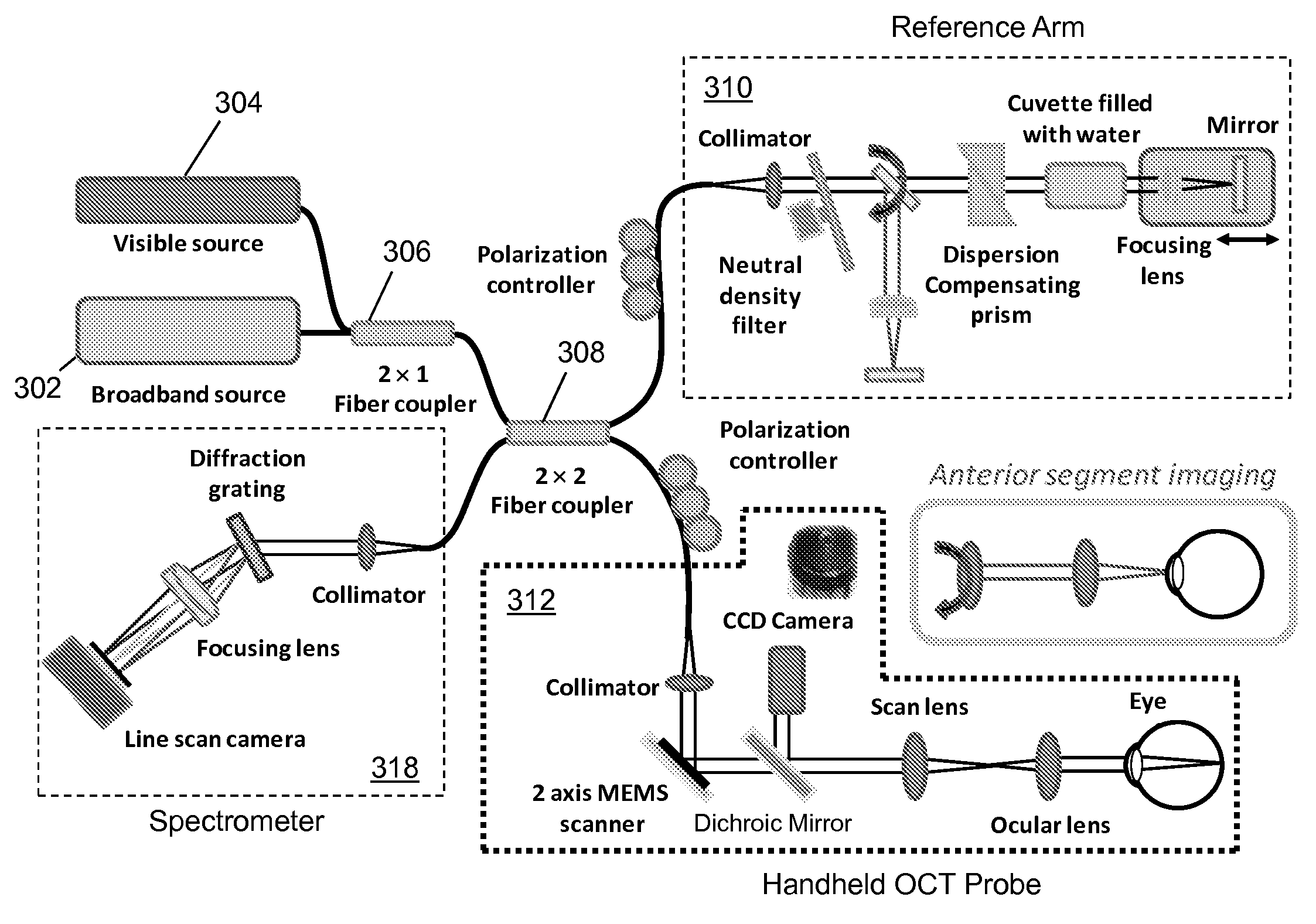
[0020]One embodiment of the present disclosure describes a medical diagnostic device having an optical coherence tomography (OCT) imaging probe. The OCT imaging probe can have a collimator, a micro-electro-mechanical system (MEMS) scanning mirror that receives one or more wavelengths of light supplied through the collimator, an image sensor, a beam splitter for splitting light reflected from a body part of a patient into first and second portions, wherein the first portion of light is supplied to the image sensor, and wherein the second portion of light is supplied to the MEMS scanning mirror, and an interchangeable module operable for coupling to the OCT imaging probe for observing the body part of the patient.
[0021]One embodiment of the present disclosure entails a computer-readable storage medium having computer instructions to generate images from spectral data supplied by an OCT imaging probe having a collimator, a MEMS scanning mirror, and a partial reflector for supplying ima...
PUM
 Abstract
Description
Claims
Application Information
 - R&D Engineer
- R&D Manager
- IP Professional
- Industry Leading Data Capabilities
- Powerful AI technology
- Patent DNA Extraction
Browse by: Latest US Patents, China's latest patents, Technical Efficacy Thesaurus, Application Domain, Technology Topic, Popular Technical Reports.
© 2024 PatSnap. All rights reserved.Legal|Privacy policy|Modern Slavery Act Transparency Statement|Sitemap|About US| Contact US: help@patsnap.com