System including plurality of storage devices and data transmission method for the same

a data transmission and storage device technology, applied in the direction of digital storage, generating/distributing signals, instruments, etc., can solve the problems of excessive consumption of current flowing in a data line, inability to take into account the reliability of communication inability to communicate between the control device installed in the printing apparatus and the storage device of the ink container, etc., to achieve accurate and high-speed data transmission and reduce consumption curren

Active Publication Date: 2011-06-02
SEIKO EPSON CORP
View PDF4 Cites 55 Cited by
  • Summary
  • Abstract
  • Description
  • Claims
  • Application Information

AI Technical Summary

Benefits of technology

[0008]An advantage of some aspects of the invention is that it provides a technique for accurate and high-speed data transmission in a system including a plurality of storage devices. Another advantage of some aspects of the invention is that it provides a technique for reducing consumed current when data are transmitted.
[0011]In the system, since the frequency of the clock signal during the identification information transmission period is set to be lower than the frequency of the clock signal during the data transmission period, it is possible to reduce the current consumption when the identification information is simultaneously transmitted to the plurality of storage devices. Moreover, since the clock signal with the higher frequency is used during the data transmission period, it is possible to transmit the data at a high speed.Application 2
[0013]With such a configuration, the connection between the storage device to which the data is not transmitted and the data signal line is set to the high impedance state during the data transmission period, thereby reducing the current consumption during the data transmission period. Moreover, since only one storage device is connected to the data signal line, the capacity component (electrostatic capacity) of the data signal line is reduced, thereby realizing the data transmission at a high speed.Application 3
[0015]With such a configuration, whether the identification information is in accordance with each other is confirmed sequentially bit by bit. When it is confirmed that the identification information in not in accordance with each other, the connection between the storage device and the data signal line is set to the high impedance state immediately, thereby quickly reducing the consumption of current by the data signal line.

Problems solved by technology

In the known technique, however, the reliability of communication between the control device installed in the printing apparatus and the storage device of the ink container is hardly taken into consideration.
For example, a problem may arise in that the communication between the control device installed in the printing apparatus and the storage device of the ink container may fail due to the contact failure of an electric connection portion between the printing apparatus and the ink container.
When the printing apparatus continues an operation in the communication failure state, a problem may arise where a fault occurs in the stored details of the storage device.
However, when the clock frequency is excessively increased, a problem may arise in that consumed current flowing in a data line is excessively increased.
In an example according to the related art, however, the study regarding this point is not sufficiently conducted.
The above-mentioned problems occur not only in the printing apparatus but also in the system including a plurality of storage devices.

Method used


Image

  • System including plurality of storage devices and data transmission method for the same
  • System including plurality of storage devices and data transmission method for the same
  • System including plurality of storage devices and data transmission method for the same

Examples


first embodiment

B. FIRST EMBODIMENT

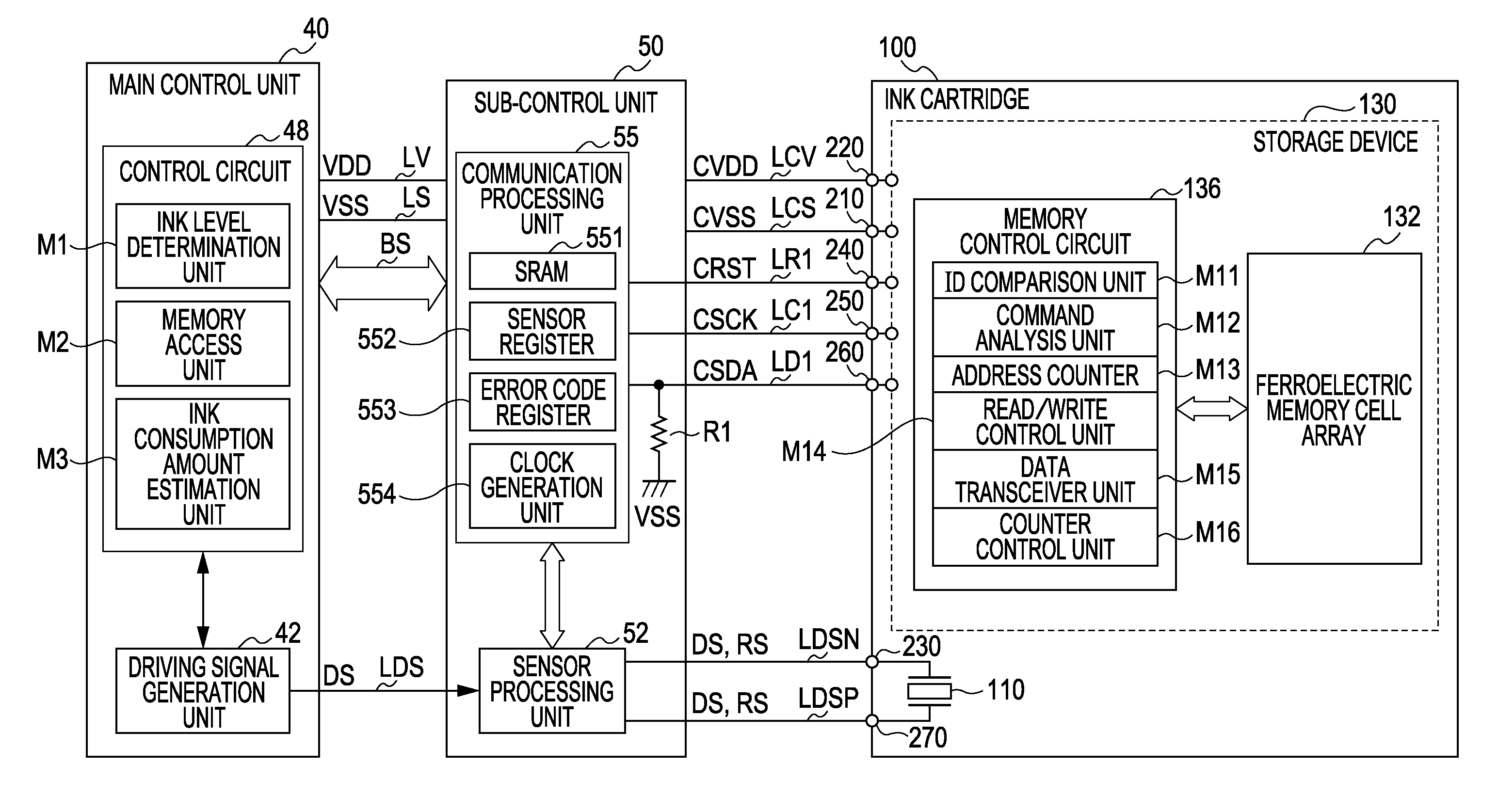
[0069]FIG. 6 is a block diagram illustrating the functional configurations of the main control unit 40, the sub-control unit 50, and the ink cartridge 100 according to a first embodiment. The main control unit 40 includes a control circuit 48 and a driving signal generation circuit 42 and includes a ROM, a RAM, and an EEPROM (all of which are not shown). The ROM stores various programs to control the printer 20. The control circuit 48 includes a CPU (Central Processing Unit) and thus controls the printer 20 as a whole in cooperation with the memories such as the ROM, the RAM, and the EEPROM. The control circuit 48 includes, as functional blocks, an ink level determination unit M1, a memory access unit M2, and an ink consumption amount estimation unit M3.

[0070]The ink level determination unit M1 controls the sub-control unit 50 and the driving signal generation circuit 42 to drive the sensor 110 of the ink cartridge 100 and determines whether the amount of ink stor...

second embodiment

C. SECOND EMBODIMENT

[0118]FIG. 12 is a block diagram illustrating the functional configuration of the main control unit 40 and the functional configurations of the sub-control unit 50 and the ink cartridge 100 according to a second embodiment and is a diagram corresponding to FIG. 6 of the first embodiment. The circuit configuration of FIG. 12 is the same as that of FIG. 6 except that a copy data generation unit M17, an inverted data generation unit M18, and a data determination unit M19 are further included in the memory control circuit 136 of the storage device 130 in FIG. 6. In the second embodiment, as described below, inverted data or mirror data is transmitted in addition to original data (also referred to as “raw data”) as the read data or the write data. The copy data generation unit M17 has a function of copying the raw data to generate the mirror data of the same amount as that of the raw data. The inverted data generation unit M18 has a function of inverting the values of...

first modified example

[0244]In the second embodiment, the raw data Dn and the inverted data / Dn are used as the data to confirm the consistency with the raw data Dn. However, other data having a predetermined logical relationship with the raw data Dn may be used instead. Specifically, the following related data may be used:

[0245](1) a copy of the raw data Dn,

[0246](2) data obtained by adding a predetermined value to the raw data Dn,

[0247](3) data obtained by subtracting a predetermined value from the raw data Dn,

[0248](4) data obtained by multiplying the raw data Dn by a predetermined value,

[0249](5) data obtained by shifting the raw data Dn by predetermined bits, and

[0250](6) data obtained through predetermined bit rotation of the raw data Dn.

[0251]In general, the raw data Dn and the data related to the raw data Dn may be used as long as the raw data Dn and the related data have a predetermined logical relationship to one another and whether there is the predetermined logical relationship between the ra...


PUM


Abstract

A system includes a plurality of storage devices and a controller. The plurality of storage devices are bus-connected to one clock signal line and one data signal line connected to the controller. Each of the plurality of storage devices stores identification information in advance to distinguish the storage devices from each other. The controller transmits data using an identification information transmission period in which one storage device is selected from the plurality of storage devices by transmitting the identification information of the one storage device to the plurality of storage devices via the data signal line and a data transmission period in which the data is transmitted to the one selected storage device. A frequency of a clock signal during the identification information transmission period is set to be lower than a frequency of the clock signal during the data transmission period.

Description

BACKGROUND[0001]1. Technical Field[0002]The present invention relates to a system including a plurality of storage devices, and more particularly, to a data transmission technique for the system.[0003]2. Related Art[0004]An ink container which is a detachable liquid container is generally mounted on an ink jet printing apparatus which is an example of a liquid ejecting apparatus. A storage device is installed in some ink containers. The storage device stores various kinds of information such as the amount of ink remaining in the ink container or the ink colors (JP-A-2002-370383 and JP-A-2004-299405). A control device installed in the printing apparatus communicates with the storage device of the ink container.[0005]In the known technique, however, the reliability of communication between the control device installed in the printing apparatus and the storage device of the ink container is hardly taken into consideration. For example, a problem may arise in that the communication betw...

Claims


Application Information

Patent Timeline
Patent Type & Authority Applications(United States)
IPC IPC(8): G06F1/06
CPCB41J2/17513B41J2/1752B41J2/17523G06K15/02B41J2/17546B41J2/17553B41J2/17566B41J2/1753
Inventor ASAUCHI, NOBORU
Owner SEIKO EPSON CORP
Why Eureka
Try Eureka