Exhaust heat recovery device

Active Publication Date: 2011-06-09
HYUNDAI MOTOR CO LTD +1
View PDF7 Cites 85 Cited by
  • Summary
  • Abstract
  • Description
  • Claims
  • Application Information

AI Technical Summary

Benefits of technology

[0025]The present invention provides an exhaust heat recovery device which is suitably configured to perform integral heat exchange between exhaust gas discharged from

Problems solved by technology

However, the technology which uses the exhaust heat in the secondary steam engine and the thermoelectric element have a considerably increased

Method used


Image

  • Exhaust heat recovery device
  • Exhaust heat recovery device
  • Exhaust heat recovery device

Examples


Example

[0040]Reference numerals set forth in the Drawings includes reference to the following elements as further discussed below:

100: recovery device110: housing120: bypass pipe130: coolant housing141 & 142: exhaust flow pipes150: oil flow pipe160: valve device

[0041]It should be understood that the appended drawings are not necessarily to scale, presenting a somewhat simplified representation of various preferred features illustrative of the basic principles of the invention. The specific design features of the present invention as disclosed herein, including, for example, specific dimensions, orientations, locations, and shapes will be determined in part by the particular intended application and use environment.

[0042]In the figures, reference numbers refer to the same or equivalent parts of the present invention throughout the several figures of the drawing.

DETAILED DESCRIPTION

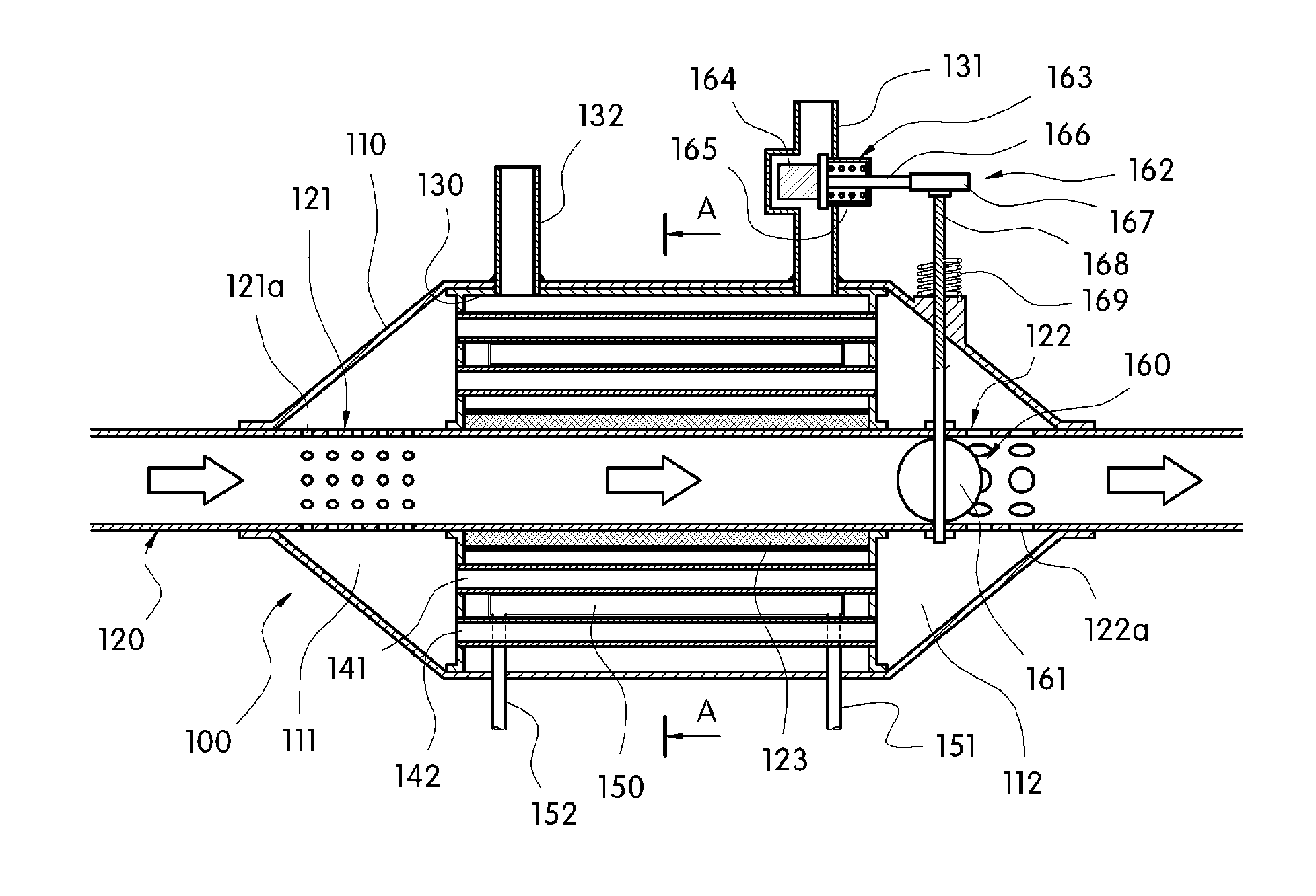
[0043]As described herein, the present invention features an exhaust heat recovery device comprising a bypass p...


PUM


Abstract

The present invention provides an exhaust heat recovery device configured to perform heat exchange between three media such as, exhaust gas, coolant, and oil. According to preferred embodiments of the present invention, the exhaust heat recovery device is configured such that the heat of exhaust gas discharged from an engine is transmitted to the coolant and the oil at the same time and direct heat exchange between the coolant and the oil is made, thereby simultaneously increasing the temperature of the coolant and the oil during the initial start-up of the engine (fast warm-up). As a result, it is possible to reduce friction loss of powertrain, thereby improving fuel efficiency. Accordingly, an object of the present invention is to provide an exhaust heat recovery device which is configured to perform the integral heat exchange between the exhaust gas, the coolant, and the oil.

Description

CROSS-REFERENCE TO RELATED APPLICATION[0001]This application claims under 35 U.S.C. §119(a) the benefit of Korean Patent Application No. 10-2009-0119661 filed Dec. 4, 2009, the entire contents of which are incorporated herein by reference.BACKGROUND[0002](a) Technical Field[0003]The present disclosure relates in general to an exhaust heat recovery device. More particularly, it relates to an exhaust heat recovery device, which recovers and reuses waste heat of exhaust gas that is discharged from an engine of a vehicle.[0004](b) Background Art[0005]Recently, research has been aimed at improving fuel efficiency by recovering and reusing energy discharged from a vehicle.[0006]Examples of technologies of recovering or reusing waste energy include:[0007](1) Thermoelectric conversion technology and thermoacoustic conversion technology using waste heat;[0008](2) Piezoelectric technology and electromagnetic induction technology using vibration and sound generated by the vehicle; and[0009](3)...

Claims


Application Information

Patent Timeline
IPC IPC(8): F01N5/02
CPCF01M5/001Y02T10/20F01N5/02F01N2240/02F01N2240/36F01N2410/00F01P2060/16F02G5/04F02G2260/00F28D7/0025F28D7/0083F28D7/1669F28D21/0003F28D2021/0089F28F9/0273F28F2250/06Y02T10/16Y02T10/166F01N3/0205Y02T10/12F28D7/00
Inventor LEE, JAE HEONMIN, BYUNG SOONKIM, SEOK JOONOHN, HYUNG SEUKCHOI, JAE YOUNG
Owner HYUNDAI MOTOR CO LTD
Why Eureka
Try Eureka